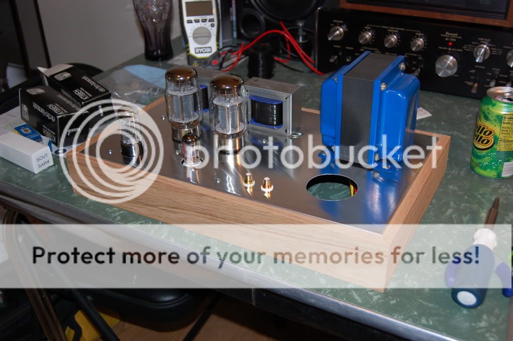
Well got my amp all wired up and double checked out everything, plug it in and in about 20 seconds or less the 5AR4 starts to flicker shut the power of but it blew the fuse already. So anyway double checked everything again and just at the point of scraching my head. I am using edcor xpwr035 for the power and gxse's for the outputs, a 100mfd 370 volt cap and a triad choke. I dont have the solid state diodes in as I don't plan on using that feature. I am running the output in UL with CF right now no switch. I also pulled the tubes and checked the voltage from the power trans and everything was reading as it should but the transformer hums???.... Any help would be great or some suggestions. Thanks
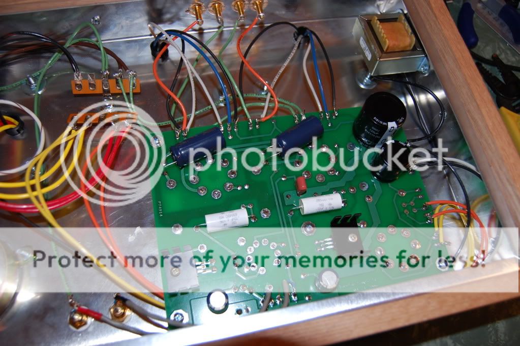
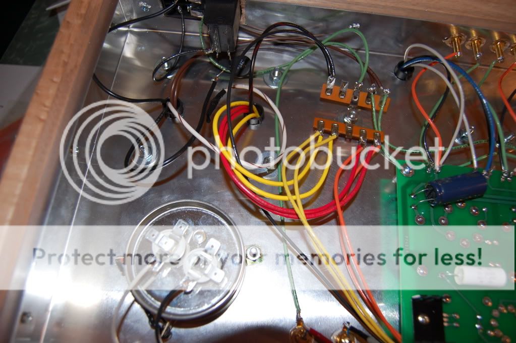
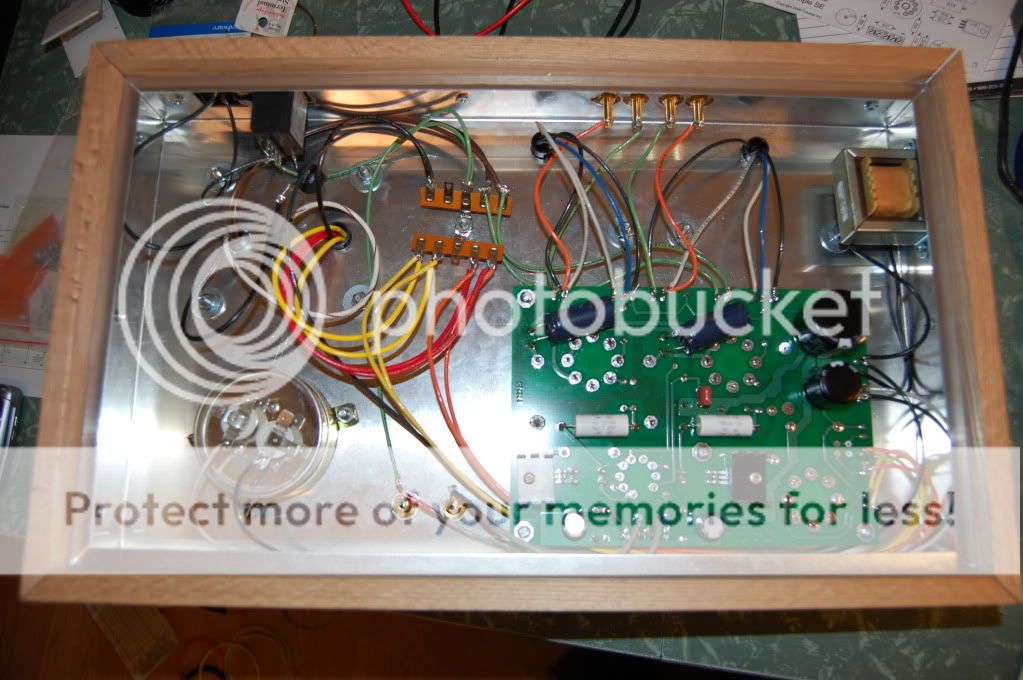
Post pictures of both sides of board and wiring of transformers. With humming of transformer indicates possible shorted/miswired connections.
Arc'ing in the rectifier tube could be caused by a number of different things:
The bad thing is that once a rectifier arcs, it is far more likely to arc again. The arc usually jumps between elements near the mica, where carbon tracks will form. This encourages future arc'ing. The only cure is replacement.
- Too much current draw, caused by a short to ground somewhere downstream of the power supply. It could be stray solder blob, or a wire whisker, or a construction mistake.
- Too much current draw, caused by power supply caps that are too big or improper biasing on the finals.
- Low quality rectifier tube. Replace with a better one, but only if you are sure #1 and #2 aren't a problem.
The bad thing is that once a rectifier arcs, it is far more likely to arc again. The arc usually jumps between elements near the mica, where carbon tracks will form. This encourages future arc'ing. The only cure is replacement.
Well just went over the board again and checked all the resistors and caps along with all the solder joints front and back and all checks out, I unhooked the transformer leads from the board and tested all taps and I am getting all the correct voltages.
Reconnected everything put in the tubes kt88's EH, 5ar4 sovtek and a jj 12at7
Yes the arcing does not happen until the rectifier tube starts to warm up, also when this happens the power transformer growls so I shut the switch off.
Ty were would you suggest to start probing??
Also I noticed that the 150 ohm 3 watt R2 in the schematic looks to have gotten a little warm but it checks out fine with my meter
I will post some pics in a few Thanks for the help
pics
An externally hosted image should be here but it was not working when we last tested it.
An externally hosted image should be here but it was not working when we last tested it.
An externally hosted image should be here but it was not working when we last tested it.
An externally hosted image should be here but it was not working when we last tested it.
What happens with just the 5AR4 installed? I assume that you don't own a variac? This would be a good opportunity to use one.
What happens with just the 5AR4 installed? I assume that you don't own a variac? This would be a good opportunity to use one.
With the 5ar4 installed it glows and does not arc at all. So is my problem down the line??
And no I do not have a variac, but my father also suggested it would be nice to use in this situation but he is 200 miles away so.....
Earlier I also took the inrush limiter out of the primary and put it in line of the CT but it still arced while warming up.
I am going to guess (based on experience) that your amp is OK and you have a bad 5AR4. The Simple SE runs the rectifier near its maximum ratings (especially with the EH KT88's), and the quality of the 5AR4's being produced today varies greatly from batch to batch. Some builders (myself included) have had to try several to find a good one. Other tube amp manufacturers have noticed this too.
The coating on the cathode and the spacing between the cathode and plate must be absolutely uniform or the cathode current will not be evenly distributed along the cathode. If the current flow is concentrated in one small area an arc WILL occur.
You say that there are no sparks with only the 5AR4 installed. Try again with the 5AR4 and the 12AT7. If there are still no sparks, measure the voltage on the plates of the 12AT7 (easilly accessed on the coupling caps). A voltage reading from 150 to 250 volts is OK.
If you got this far without sparks, try adding one KT88. If there are no sparks test to see if the amp is working on that one channel. Try the other channel (one at a time). If both channels work individually but sparks happen when both are used, the rectifier tube is bad.
If the rectifier tube sparks when either KT88 is installed it is likely bad, but this can not be easilly confirmed. If you have some different values of 5 watt resistors available you can set the current through the KT88's to a lower value (higher resistor value) and test again.
Sounds like a short downstream of the rectifier.
Use a multimeter on ohms setting to check for shorts.
Use a multimeter on ohms setting to check for shorts.
Just tried with the 5ar4 and the 12at7 and I get some arcing
Are you saying as in a short to ground??
Sounds like a short downstream of the rectifier.
Use a multimeter on ohms setting to check for shorts
Are you saying as in a short to ground??
Just wondering, is the 10m45 installed backwards? since it is installed under the board, K should be to r13 and A to r14. Pinout is GAK http://ixdev.ixys.com/DataSheet/98704.pdf.
Just a thought.
Just a thought.
Also I noticed that the 150 ohm 3 watt R2 in the schematic looks to have gotten a little warm but it checks out fine with my meter
Is this a typo? R2 is 150,000 ohms not 150 ohms. This will surely cause arcing in the rectifier if that is what is actually in your amp.
Is this a typo? R2 is 150,000 ohms not 150 ohms. This will surely cause arcing in the rectifier if that is what is actually in your amp.
Is this a typo? R2 is 150,000 ohms not 150 ohms. This will surely cause arcing in the rectifier if that is what is actually in your amp.
Nope thats what it is. You have found it!!!!! I just removed it from the board and it is toast. I guess when I ohmed it out it was picking up R4 in the circuit.
Wonder what else is toast???
Looked at my digikey order from the parts and shure enough I forgot the K $#%$# !!!
I ordered some 150K and some new 10m45's and some new caps just incase.
I also would guess that I will need a new 5AR4??
Wonder what else is toast???
R2 is a 150K (150,000 ohms) resistor. Its sole purpose is to provide a discharge path for the power supply caps. This "bleeds" off the stored charge in the capacitors when the amp is turned off. Operating the amp with a 150 ohm resistor subjected the 5AR4 to an extreme overcurrent situation, which made it protest with fireworks. It is likely damaged, but I have seem some tubes survive this. R2 is a redundant bleeder resistor. The combination of R3 and R4 will also discharge the capacitors but at a slower rate. You may try the amplifier with R2 removed, but it must be replaced before putting the amp in service. I like to have a bleeder on each power supply cap in case a wire gets disconnected, or the choke fails.
It is not possible to figure out how you have the 10M45's wired from the pictures. I dont believe that the 10M45's are damaged.
I would try the amp again with R2 removed, If it still sparks out the 5AR4 is likely toast. If there is no fireworks, measure the voltage on the coupling caps, and report back.
Did a quick check with just the 5AR4 in and no arcing at all. Checked the voltage at the coupling caps and I am showing 540vdc. Off to work for now. Everyone have a good day.
Checked the voltage at the coupling caps
Install the 12AT7 and measure the voltage at the coupling caps (the white ones). You should have zero volts at the end connected to the output tubes, and 150 to 250 volts at the end connected to the 10M45's. If this voltage is OK the 10M45's are OK. Try adding the output tubes and see what happens.
Do not run the amp for extended periods of time without all of the tubes in place. As your voltmeter tells you the power supply can produce over 500 volts when it has no load. This is more than the 500 volt rated capacitors can take for extended periods of time. They can be real messy when they blow up too!
Do not run the amp for extended periods of time without all of the tubes in place. As your voltmeter tells you the power supply can produce over 500 volts when it has no load. This is more than the 500 volt rated capacitors can take for extended periods of time. They can be real messy when they blow up too!
I always worried about that. I wish there were an easy source for 550 (working voltage) rated snap-in electrolytics. It seems the only affordable recourse is to go with motor run caps and mount them somewhere off the board.
I think the Panasonic caps I put in mine (the recommended part from Digi-Key) is surge rated for 550 volts. Unfortunately, I've never seen a length of time specified for the duration of the surge.
I think the Panasonic caps I put in mine (the recommended part from Digi-Key) is surge rated for 550 volts. Unfortunately, I've never seen a length of time specified for the duration of the surge
I have never seen this specified either. The (over) voltage handling ability of most electrolytics are highly temperature dependent.
I can say that I hooked up a big Antek 400-0-400 volt toroid to a Simple SE board to see what happens. I got about 530 volts of B+. The EH KT88's seemed to deal with this OK and nothing fried. I ran the amp for no more than an hour at a time for about a week before dismantling it. I use that same board for all of my extreme experiments and I have blown it up at least a dozen times, but the original Panasonic caps are still hanging in there.
While finding the upper limit of Pete Milletts "red board" I managed to explode a 450 volt Nichicon electrolytic. It operated at 450 volts for an hour right next to some toasty sweep tubes before I decided to crank up the power supply. The cap exploded rather violently at 600 volts. Hey I wound up extracting a reliable 250 watts from an amp designed for 18 WPC. Sacrificing a few parts in the name of science is OK by me, but most Simple SE builders would rather not have their amps explode.
http://www.diyaudio.com/forums/tubes-valves/151206-posted-new-p-p-power-amp-design.html
Well I got my 150k ohm restitor and checked with my VM. Got it install put the 5ar4 fired it up no arcing, shut it off put the 12at7 in after awhile fire her up and starts to arc hmm?? So the quest continues.
The 12AT7 and its associated components can not possibly draw enough current to arc a healthy 5AR4. The 12AT7 gets its supply voltage through a pair of 10K resistors. Assuming the resistors are indeed 10K, everything after that (10M45's and 12AT7's) could be shorted out and the 5AR4 shouldn't arc. I must assume that your 5AR4 was injured by the arcing that it saw with the 150 ohm resistor.
- Status
- Not open for further replies.
- Home
- More Vendors...
- Tubelab
- Need Some SimpleSE Help