I'm pretty new to transistors but would like to experiment with CCS as a anode load (eg B+ up to 500V and Ip up to 50mA).
I've read Morgan Jones' intro to CCS and believe for anode load CCS I need PNP transistors.
His table on p139 lists out the following parameters Vce(max), Ic(max), Pmax,ft, hFE (min) and 1/hoe(typ).
Unfortunately being in Japan I cannot readily acquire the recommended MJE350 nor MPSA92 so I would like to source some local alternatives.
Are these the only parameters I need to watch out for in selecting the power transistor?
eg would the 2SA1486 be a good choice?
http://www.classiccmp.org/rtellason/transdata/2sa1486.pdf
Many thanks!
Jeff
Yes, "P" type semiconductors are better for constant current sources, as the high impedance electrode (collector or drain) feeds the tube. However, GOOD results have been achieved with "N" type stuff. Check the work of Gary Pimm out.
FWIW, I'm a MOSFET, as opposed to BJT, fan. If Fairchild semiconductors are available to you check the FQP3P50 out.
FWIW, I'm a MOSFET, as opposed to BJT, fan. If Fairchild semiconductors are available to you check the FQP3P50 out.
FWIW, I'm a MOSFET, as opposed to BJT, fan.
So am I. I've gotten excellent results from bipolar cascodes, but MOSFET cascodes (using n-channel) are even better and simpler.

So am I. I've gotten excellent results from bipolar cascodes, but MOSFET cascodes (using n-channel) are even better and simpler.
I wonder if something could be made of a DN2540 "upstairs" and a FQP3P50 "downstairs". A 100 Ω resitor between the 2 source electrodes would provide a test point and reverse bias for the depletion mode FET. A 1 MOhm pot. sitting between B+ and ground would have its wiper connected to the enhancement mode "P" channel FET's gate.
there are depletion mode mosfets that would work as two terminal ccs without the extra pass Q
IXYS
IXTP01N100D
VDSS, max, (V) 1000
ID(cont), TC=25°C, (A) 0.1
RDS(on), max, VGS = 0 V, (Ω) 110
VGS(off), max, (V) -5
Ciss, typ, (pF) 120
Crss, typ, (pF) 3
Qg, typ, (nC) 5
PD, (W) 25
http://ixdev.ixys.com/DataSheet/98809.pdf
I've purchased them from Mouser @ US$0.80 ea
IXYS
IXTP01N100D
VDSS, max, (V) 1000
ID(cont), TC=25°C, (A) 0.1
RDS(on), max, VGS = 0 V, (Ω) 110
VGS(off), max, (V) -5
Ciss, typ, (pF) 120
Crss, typ, (pF) 3
Qg, typ, (nC) 5
PD, (W) 25
http://ixdev.ixys.com/DataSheet/98809.pdf
I've purchased them from Mouser @ US$0.80 ea
there are depletion mode mosfets that would work as two terminal ccs without the extra pass Q
IXYS
IXTP01N100D
VDSS, max, (V) 1000
ID(cont), TC=25°C, (A) 0.1
RDS(on), max, VGS = 0 V, (Ω) 110
VGS(off), max, (V) -5
Ciss, typ, (pF) 120
Crss, typ, (pF) 3
Qg, typ, (nC) 5
PD, (W) 25
http://ixdev.ixys.com/DataSheet/98809.pdf
I've purchased them from Mouser @ US$0.80 ea
IXYS' 10M45S has acquired considerable notoriety. The problem with single device setups is a comparatively low dynamic AC impedance. Cascodes do much better in that important dept. One device = good. Two devices = better.
agreed, cascode is good for ccs
depletion mode enables two terminal floating ccs with more complex current regualtion if needed
this simulated circuit is limited by Crss (~5 pF for IXTP01n100) |Z|> 1 MOhm @ 20 KHz
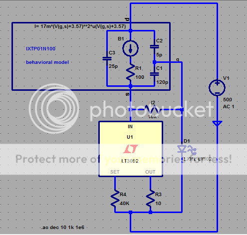
MOSFET model uses fit to measured gm points, datasheet C
depletion mode enables two terminal floating ccs with more complex current regualtion if needed
this simulated circuit is limited by Crss (~5 pF for IXTP01n100) |Z|> 1 MOhm @ 20 KHz
MOSFET model uses fit to measured gm points, datasheet C
Attachments
Last edited:
Thank you guys.
For the first attempt, I'll go with the 'P' BJT in a cascode config.
I need a bit of time to get my head around any transistor design that gets more complicated than that!
For my next trick, perhaps MOSFETs.
Neither the IXYS nor the FQP3P50 are available locally, so for MOSFET based CC Source I would need to find alternatives.
Would the key parameters to meet be VDSS, ID, PD?
If so how does the 2SJ117 stack up (for 400V)?
http://www.classiccmp.org/rtellason/transdata/2sj117.pdf
Thanks again,
Jeff
I wonder if something could be made of a DN2540 "upstairs" and a FQP3P50 "downstairs". A 100 Ω resitor between the 2 source electrodes would provide a test point and reverse bias for the depletion mode FET. A 1 MOhm pot. sitting between B+ and ground would have its wiper connected to the enhancement mode "P" channel FET's gate.
Well, the simple DN2540 cascode that I use has 5 parts (the two FETs and three resistors), 100M source impedance and <12pA/rt Hz noise, so I'm not tempted to gild the lily.

I have a nice MOSFET CCS design (source and sink) that has proven itself quite well
Cheers!
Why not eliminate the top 2N3904 and use the FET in it's place (reduces to a "Ring of Two" current source)? Stability? That is what I did on a simulation at work about 4 months ago and it looked like it would work fine. I never incorporated it in my design because a 100V 1W bipolar transistor is cheaper than a 100V 1W FET. $.04 matters.
I just used the "Ring of Two" current source with both bipolar transistors. This is combined with 3ms filter so hf oscillations are not as much of a concern.
Because that was not the design.
This one I used is based on ultimate stability into many conceivable loads (in practise, not Spice) and versatility.
Cheers!
Jeff,
I live in Tokyo, it would be good to share some experience locally, where are you based ?
I also had a bit of problems in finding some components in the shops, but I think I solved it ordering them on Mouser Electronics - Electronic Component Distributor. The site is in english, but it has a Japanese branch.
Best Regards,
Davide
SY....can you please gild that lily some.(a scemo and some maths or a thead maybe a post)
Sorry, missed this post. See the ImPasse preamp article in the Feb 09 AX, Walt Jung's analysis of that CCS in March 09 AX, and the soon-to-appear here phono preamp article. I think I've also put a schematic of the CCS up here sometime in the past year- try a search for "DN2540 cascode" with me as the poster.
I have a nice MOSFET CCS design (source and sink) that has proven itself quite well
Gregg qq:
The Isink output here is used for the anode/plate?
Could this be used to dissipate 800mA or more in substitution for a plate resistor?
110V being used only but high current.
Thanks
Attachments
- Status
- This old topic is closed. If you want to reopen this topic, contact a moderator using the "Report Post" button.
- Home
- Amplifiers
- Tubes / Valves
- CCS transistor choices