I have worked on a vacuum tube (12AX7/ECC83) based RIAA preamplifier in simulation, and I just wanted to show it to you and hear opinions and inputs. It's nothing spectacular, and it could probably be done in a better way. I have not had the time yet to build it, and have only been able to test it by simulation (Multisim 10). I will of course build some time in the future.
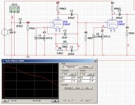
The circuit is very simple built with a double triode (12AX7/ECC83) for each channel. It is built as two single voltage amplifiers, where the first one has the RIAA compensation in the negative feedback path, and the second one does some voltage amplification. The nominal gain at 1 kHz is around 39.5 dB (with a 47k load). The gain at 100 Hz is around 50.5 dB and at 10 kHz is 27 dB, this is matching the RIAA curve quite accurately (at least in simulation). The curve flattens out a bit at 40 Hz and down, and though that's not following the RIAA curve exactly, but it decreases subsonic amplification, hence rumble and such. The supply voltage has been set to 250 volts, which is maybe a bit more than necessary. The amp could be driven without problems all the way down to less than 100 Volts, though the gain will be significantly lower with lower supply voltages. All caps should be rated at least at supply voltage, the resistors should be rated 1/4 Watt, preferrably metal film 1% although 5% carbon film could be used. One could perhaps measure the resistors to nominal values. The values in the circuit has been tweaked to compromise between the E12 values and the requirements of the RIAA curve.
The input impedance of the circuit is determined by R5 (the 47k resistor between the grid and ground), and could easily be tweaked to ones preferance. I have chosen 47k as input impedance since this is the typical "industry standard" input impedance in most RIAA amps. Measurements in the simulations gives an output impedance of around 28kohms, which will easily drive a line in/aux in which is typically 47k. If the output impedance needs to be lower. The output impedance could be made significantly lower by adding a buffer or emitter follower.
I would like to hear inputs from you, what I did right and wrong, what could be better.
Attachments
1/ Normally a feedback 12AX7 type of phono stage loops the NFB around two tubes, as one tube like you have will not provide enough loop gain to allow accurate following of the 40dB loss of the RIAA network.
2/ With the 100uF cathode bypass cap (C1) you will not get any RIAA eq, as the AC feedback will be shorted to gnd. So I have no idea how you can get RIAA eq in your simulations, but I know that in real life, it will NOT have RIAA eq.
Regards, Allen
2/ With the 100uF cathode bypass cap (C1) you will not get any RIAA eq, as the AC feedback will be shorted to gnd. So I have no idea how you can get RIAA eq in your simulations, but I know that in real life, it will NOT have RIAA eq.
Regards, Allen
Since the plate and cathode are in phase there is no negative feedback through the EQ network at all. (The 220uF cathode bypass cap turns this into a very poor implementation of passive feedback in fact.) Normally a lot more gain is required to realize the proper response with feedback based equalization - the minimum open loop gain should be significantly > 70dB from 20Hz - 20kHz to assure some level of accuracy at the bottom end.
The frequency dependent loading imposed on the plate circuit of that first stage by your EQ network is responsible for any EQ actually occuring.
In an application like this passive EQ would probably be more effective - something based on the work of Stanley Lipshitz at U of Ontario. There are some very simple phono stage designs on my site that work. (Note these are 20yr old designs, if interested I can advise on improvements.)
Last edited:
I have worked on a vacuum tube (12AX7/ECC83) based RIAA preamplifier in simulation, and I just wanted to show it to you and hear opinions and inputs. It's nothing spectacular, and it could probably be done in a better way. I have not had the time yet to build it, and have only been able to test it by simulation (Multisim 10). I will of course build some time in the future.
<snip>
Measurements in the simulations gives an output impedance of around 28kohms, which will easily drive a line in/aux in which is typically 47k. If the output impedance needs to be lower. The output impedance could be made significantly lower by adding a buffer or emitter follower.
I would like to hear inputs from you, what I did right and wrong, what could be better.
Actually you will quite quickly find out that this circuit will not drive a 47K load very well. (Low gain and poor distortion performance.) To be effective in so doing the driving impedance for distortion and gain considerations should be < 1/10 the load impedance.
The 12AX7A has an rp of typically 66K or higher and for good thd performance and reasonable gain the combined load represented by the plate load resistor and the next stage should ideally be >3X - so figure on a 200K load resistor and an input impedance of around 1M or so for the following stage.
Given the limited current capability of the 12AX7A you might want to consider using a cathode follower if you really want to drive a 47K load with this thing, and that CF should use a higher transconductance triode like the 6CG7 running at 5mA or so to do the job..
Before proceeding any further I would pick up a copy of Morgan Jones' "Valve Amplifiers" 3rd edition and read it, paying particular attention to the section on phono pre-amplifier design.
Link to book at AudioXpress: http://www.audioxpress.com/bksprods/products/bkb40.htm
At Amazon: http://www.amazon.com/gp/product/07..._m=ATVPDKIKX0DER&pf_rd_r=0CQDQH59FBDERGASQMN2
At Amazon (Kindle Edition): http://www.amazon.com/gp/product/B0..._m=ATVPDKIKX0DER&pf_rd_r=0GK3RFG9DAB8D1XYE21J
FWIW: I recommend AudioXpress as they are the only diy audio magazine operation left standing in the USA, and sales through their bookstore help to keep them alive. (I have no affiliation or connection with them.)
Last edited:
Oops, I almost feel embarrased ajour that. Well did know the fact that simulation wont always tell The truth. This is my very first vacuum tube circuit, although I have made plenty of solid state circuits including transistor and opamp based RIAAs. I am by the way under education as an electronics technician and are almost done, so I have pretty good knowledge about electronics. Well, tube-beginner mistake and I apologise ")
They sadly do not teach us anything at school about "ancient" technologies as tubes. When I get the circuit right and get time to build and test it I'll try to post it here again
They sadly do not teach us anything at school about "ancient" technologies as tubes. When I get the circuit right and get time to build and test it I'll try to post it here again
I would guess that your simulation is alright but as Kevin points out it is a passive eq.
If you just return your eq to ground instead of tho the cathode of the first ax7 and add a buffer for drive you will probably have a decent phono stage, but with potential for improvements...
I definetey second the reading of Jones' book.
/Olof
If you just return your eq to ground instead of tho the cathode of the first ax7 and add a buffer for drive you will probably have a decent phono stage, but with potential for improvements...
I definetey second the reading of Jones' book.
/Olof
Oops, I almost feel embarrased ajour that. Well did know the fact that simulation wont always tell The truth. This is my very first vacuum tube circuit, although I have made plenty of solid state circuits including transistor and opamp based RIAAs. I am by the way under education as an electronics technician and are almost done, so I have pretty good knowledge about electronics. Well, tube-beginner mistake and I apologise
They sadly do not teach us anything at school about "ancient" technologies as tubes. When I get the circuit right and get time to build and test it I'll try to post it here again
Ancient? Perhaps, but hardly obsolete. When SS devices become as linear as triode vacuum tubes, it will be front page NY Times news.
In addition to the writings of Morgan Jones, try to scrounge up a copy of either the 1st or 2nd edition of James Brophy's "Basic Electronics for Scientists". Brophy rigorously teaches the theory of both tubes and SS.
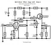
I've uploaded a schematic for a tweaked version of RCA's "classic" passive EQ design. As you are trying to, RCA built around the 12AX7. Unlike the RCA original, the tweaked variant has decent load driving capability and bass extension is better too. If the uploaded schematic whets your appetite, I'll provide some value corrections and suggestions to hold the cost down. The drawing was made by Buzz, from a narrative I provided. Buzz loves pricey, boutique, parts.
Attachments
- Status
- This old topic is closed. If you want to reopen this topic, contact a moderator using the "Report Post" button.
- Home
- Amplifiers
- Tubes / Valves
- My own RIAA tube preamp