I just finished an EL84 push-pull amplifier using Electro-Harmonix (EL84EH) tubes. I'm running 300V B+ and a shared bypassed 110 Ohms cathode resistor. Each EL84 also has it's own 2 Ohm (unbypassed) cathode resistor to measure bias current, and I'm using a 10 Ohm potentiometer to adjust the bias balance between the two tubes. Total, each EL84 has 117 Ohms cathode resistance.
This results in about 47mA bias current per tube, making the plate dissipation around 13.5 Watts. This is a little higher than the rated 12W.
Are the EL84EH capable of this plate dissipation, or should I adjust the plate current down a little bit (i.e. 43mA)?
This results in about 47mA bias current per tube, making the plate dissipation around 13.5 Watts. This is a little higher than the rated 12W.
Are the EL84EH capable of this plate dissipation, or should I adjust the plate current down a little bit (i.e. 43mA)?
Hi Kashmire,
in general, it is not a good idea to run power tubes at or in excess of their max. Pda, since tube wear is not a linear function. For example, running at about 80% of their max. Pda may even double the operation hours you can get from them, depending on type. Which might make a difference to your wallet.
Regards,
Tom Schlangen
I would turn it down a little. I've seen some varieties begin to shown signs of excess dissipation with as little as 400 volts * 30 mA (plate plus screen). Turn off all the lights in the room, and allow your eyes to adapt to the dark. With the amp fully warmed up, can you see any hints of red color anywhere on the plates?
Turn off all the lights in the room, and allow your eyes to adapt to the dark. With the amp fully warmed up, can you see any hints of red color anywhere on the plates?
Another way to tell before your eyes can is to use a digital camera - their CCD's are quite sensitive to shortwave infrared.
Cheers!
Another way to tell before your eyes can is to use a digital camera - their CCD's are quite sensitive to shortwave infrared.
I use a Digital camera to confirm a working remote this way...
Great idea on the digital camera. I'll give it a try to see if the plate is glowing.
BTW, I was reading Manno Van Der Veen's book last night (a.k.a. Plitron Transformers), and he recommends running EL84s slightly over their plate dissipation limit. He runs his at 330V 40mA = 13.2W.
BTW, I was reading Manno Van Der Veen's book last night (a.k.a. Plitron Transformers), and he recommends running EL84s slightly over their plate dissipation limit. He runs his at 330V 40mA = 13.2W.
Kashmire,
Don't forget the fact that your 47 mA. of cathode "idle" current is partitioned between the plate and g2. Look at the GE 6BQ5 data sheet. The design center limit for the combined dissipation is 14 W. Design center limits are conservative and a 10% increment is usually safe. 10% above design center is design maximum, which is self explanatory.
You are pushing the tubes hard, but not grotesquely. The IR image idea makes sense to me.
Don't forget the fact that your 47 mA. of cathode "idle" current is partitioned between the plate and g2.
An excellent point which is worth mentioning, although I believe Kashmire is already well aware of this. He stated his B+ was 300 volts DC, and total idle current was 47 mA per tube. This would amount to 14.1 watts total dissipation, of which Kasmire calculates (estimates?) 13.5 watts to the plate. The remainder would logically fall on the screen.
IR digital photography is an interesting subject as well. The internet abounds with good discussion of the subject. One might be found here: Infrared basics for digital photographers
The relevant point is that not all digital cameras are equally sensitive to IR. In fact, most modern digital cameras are built with internal IR filters designed to block out the IR, and make them less sensitive. Try to find an older digital camera (i.e., 1999 vintage - roughly 2 MP). It might also work to use one of the Sony Handycam or equivalent equipped with a "night vision" mode. These cameras are equipped with an IR illuminator so they can light up the subject without creating visible light. According to legend, some models were so sensitive to IR they could "see through clothes". In the presence of strong IR lighting (sunlight) and appropriately inappropriate clothing (thin, dark material) the IR would penetrate right through the fabric and the camera could "see" right through.
I’m not in favor of choosing to violate specs during a design phase, but much of the world did just that in the past with el84s. As an example, guitar amps abuse el84s, at least on paper, more than any of the other common output tube they use. I haven't seen a circuit yet that isn't violating at lest one of "the mans" guidelines. ") I use a resistor to reduced the PS voltage, and a higher cathode resistor to reduce the current in the pair I have in my 1967 Harmony. Also put in a bias pot to fine tune. Certainly all unnecessary, but it made me feel better during the initial overhaul I gave it. It seems to me that the specs on el84s can be (or at least are) violated to a greater extent than others, for whatever reason.
I use a resistor to reduced the PS voltage, and a higher cathode resistor to reduce the current in the pair I have in my 1967 Harmony. Also put in a bias pot to fine tune. Certainly all unnecessary, but it made me feel better during the initial overhaul I gave it. It seems to me that the specs on el84s can be (or at least are) violated to a greater extent than others, for whatever reason.
I use a resistor to reduced the PS voltage, and a higher cathode resistor to reduce the current in the pair I have in my 1967 Harmony. Also put in a bias pot to fine tune. Certainly all unnecessary, but it made me feel better during the initial overhaul I gave it. It seems to me that the specs on el84s can be (or at least are) violated to a greater extent than others, for whatever reason.I measured 10.4 Volts across the shared 110 Ohm cathode resistor, which is 47mA per tube. Another volt is lost across each tube's separate current sense resistor (2 Ohms) and trimpot (10 Ohms). The B+ is actually (301 - 12) = 289, so the power is 289 * 0.047 = 13.6W per tube (measured at the cathode). I have 1k resistors on the screens (this was a mistake, I will be changing to 150 Ohms), so the screens aren't contributing much power dissipation.
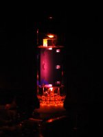
Pictures attached. Plate seems to be "glowing"? Might have to dial down the current a little bit. With 300V B+, each 10 Ohms of cathode resistance changes each tube's bias current approximately ~2mA. Will change the cathode resistor to 120 (45mA) or 130 (42 mA), and also change those screen resistors while I have the soldering iron hot.
Pictures attached. Plate seems to be "glowing"? Might have to dial down the current a little bit. With 300V B+, each 10 Ohms of cathode resistance changes each tube's bias current approximately ~2mA. Will change the cathode resistor to 120 (45mA) or 130 (42 mA), and also change those screen resistors while I have the soldering iron hot.
Attachments
Oooo! That's hot.
I find the 6P1P (similar to EL84/6BQ5/6AQ5, but with slightly lower plate voltage and PD) is slightly red along the plate seam at 13.5W and plan on backing down.
It seems to me that I can see the red out of my peripheral vision better than I can looking at it straight on.
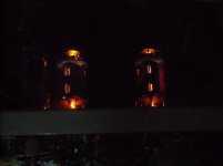
Here is the worst I've driven mine in comparison to yours. Mine is streaking from the center of the fin up and down, but not to the area of the plate that is actively driven.
I'd certainly recommend dropping your cathode current slightly to improve longevity.
I find the 6P1P (similar to EL84/6BQ5/6AQ5, but with slightly lower plate voltage and PD) is slightly red along the plate seam at 13.5W and plan on backing down.
It seems to me that I can see the red out of my peripheral vision better than I can looking at it straight on.
Here is the worst I've driven mine in comparison to yours. Mine is streaking from the center of the fin up and down, but not to the area of the plate that is actively driven.
I'd certainly recommend dropping your cathode current slightly to improve longevity.
Attachments

http://s69.photobucket.com/albums/i43/Ty_Bower/Tubes/P1070379.jpg
http://s69.photobucket.com/albums/i43/Ty_Bower/Tubes/P1070380.jpg
Here are my "too hot" photos. It's easier to see it in in the dark, but I think you can still find the hint of red glow on the left tube, even in the room lit picture.
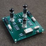
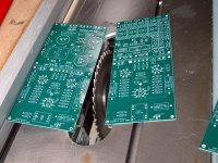
Kashmire - Neat circuit board, by the way. Where did you get it?
Kashmire - Neat circuit board, by the way. Where did you get it?
Made it with ExpressPCB. I occasionally need to make some circuit boards for work projects. Since ExpressPCB offers a 12"x14" maximum size, I usually make four 6"x7" boards and cut them apart with my table saw.
The bulk of the cost of ExpressPCB is the "setup fee". The incremental cost between a single 6"x7" board and a whole 12"x14" pizza platter is small.
Therefore, in this case, I needed to build a digital sensor board for a work project (upper right board).
So, I threw in a 300V B+ power supply (upper left), EL84 push-pull with LL1540 (bottom left), and EL84 push-pull with Edcor (bottom right).
My next PCB project will include: KT-88 SE, a driver stage for my massive KT-88 push-pull, and a better power supply board (which will also be capable of up to 425V B+).
Attachments
I have just come across your post about the EL84.I just finished an EL84 push-pull amplifier using Electro-Harmonix (EL84EH) tubes. I'm running 300V B+ and a shared bypassed 110 Ohms cathode resistor. Each EL84 also has it's own 2 Ohm (unbypassed) cathode resistor to measure bias current, and I'm using a 10 Ohm potentiometer to adjust the bias balance between the two tubes. Total, each EL84 has 117 Ohms cathode resistance.
This results in about 47mA bias current per tube, making the plate dissipation around 13.5 Watts. This is a little higher than the rated 12W.
Are the EL84EH capable of this plate dissipation, or should I adjust the plate current down a little bit (i.e. 43mA)?
I'm building (slowly) a Tubelab http://tubelab.com/designs/tubelab-spp/ amp and it uses 4 x EL84's, my build is with Sovtek's.
The build shows the cathode resistor value of 270R. The design does not have a bias adjustment.
I have seen some DiyAudio views saying if the supply voltage is 320V, the final dissipation works out at 13.47 Watts, that apparently is a bit high.
What is the safe dissipation wattage?
- Home
- Amplifiers
- Tubes / Valves
- EL84 Plate Dissipation