hey-Hey!!!,
There is no way to do this for PP with a single screen supply. SE would be possible, but the U-L behaviour from a fixed supply is IME a benefit. McIntosh solved the PP implementation quite elegantly, but it requires g2 voltage equal to the plate.
cheers,
Douglas
Yes, of course it would take one supply per tube. I guess it would only make sense to go through the effort where there is a lot of cathode swing, for example for a cathode follower output stage. Back to my question, does anybody do it? Is the stray capacitance of such a supply an issue? I'm just curious. I'm not likely to ever try it myself.
You guys can argue all you want about UL vs. CFB. However, I will tell you that in my experiments the CFB setup sounded more focused and resolved the nuances better than UL connection. Image stability was also better.
Hey JLH,
Great to hear you have done some evaluations. Have tried to look into what happens in your IRL test. This can be a plausible explanation/guesswork of your findings:
There is a radical difference between UL and CFB as you can have as high local feedback as you like without loosing tetrode/pentode power. You only loose sensitivity. While UL can only go to triode-strapped with lost max power, CFB can go beyond triode-strapping and still have the max power of the tetrode/pentode. Something that points in that direction is that a 15% CFB has almost half of the Zout as a triode-strapped. Very much like Schadeing but keeping the high Zin of tetrode/pentode, only more signal voltage is needed..
One must also remember 15% CFB is a lot more than 40% UL. With 15% CFB(at just below 20dB) you can skip GFB while std 40% UL(ca 10dB) needs GFB to lower Zout and distortion. When going 15% UL, output will be almost on par with triode-strapping so what made Hafler(?) and the boys decide about 43% is probably a compromise between max power and bettered performance.
Hey JLH,
There is a radical difference between UL and CFB as you can have as high local feedback as you like without loosing tetrode/pentode power. You only loose sensitivity. While UL can only go to triode-strapped with lost max power, CFB can go beyond triode-strapping and still have the max power of the tetrode/pentode. Something that points in that direction is that a 15% CFB has almost half of the Zout as a triode-strapped. Very much like Schadeing but keeping the high Zin of tetrode/pentode, only more signal voltage is needed..
One must also remember 15% CFB is a lot more than 40% UL. With 15% CFB(at just below 20dB) you can skip GFB while std 40% UL(ca 10dB) needs GFB to lower Zout and distortion. When going 15% UL, output will be almost on par with triode-strapping so what made Hafler(?) and the boys decide about 43% is probably a compromise between max power and bettered performance.
hey-Hey!!!,
CFB needs to be implemented so that the g2-k voltage remains constant; feeding g2 from a fixed supply gives U-L operation at what ever percentage of CFB is applied. McIntosh found one way...floating supply is another, a separate coil will have similar results.
Hafler and Co picked a reasonable compromise, tubes with sensitive g2( like sweeps ) do very well with low U-L/CFB fractions. Types like 6L6, KT88 and the like higher percentage. Tubes like 6V6 can't deliver much above triode power with high percentage U-L, there just isn't enough current capability at low g2 voltage to swing the plate low( highest current, lowest g2 voltage ).
With a Dynaco A441 I tried using the tertiary coil for U-L and CFB, and my result was very similar to JLH; CFB stayed...
") even with the KT90 outputs rigged triode mode( thogh CFB rigged for ~17% U-L operation was better in terms of both sonics and output power ).
even with the KT90 outputs rigged triode mode( thogh CFB rigged for ~17% U-L operation was better in terms of both sonics and output power ).cheers,
Douglas
Do you know this two Studer studio amplifiers out of the fifties?
First, the model 52, based on EL84 (PDF):
ftp://ftp.studer.ch/Public/Products/Miscellaneous/Model_52_PwrAmp/Manuals/Model_52_Diagr.pdf
For this amp, you can order OPT's from Gerd Rheinhöfer () , the type 53.1S52, built on the original OPT's datas, but more symmetrically.
And the "same" circuit, using EL34's: The model 22
[url]ftp://ftp.studer.ch/Public/Products/Miscellaneous/Model_22_PwrAmp/Manuals/Model_22_Diagr.pdf
This circuit could work very well with the Lundahl LL1620CFB OPT.
During my time working with Studer, I found this two circuits in the archive.
Franz
Last edited:
hey-Hey!!!,
I was not familiar with that maker. Looks pretty standard, commercial design to me. I much prefer to use enough CFB so as to eliminate the need for the global loop, or do additional local( Schade, RCA SP20, or E-Linear )on the output stage. Thanks for showing it.
cheers,
Douglas
I was not familiar with that maker. Looks pretty standard, commercial design to me. I much prefer to use enough CFB so as to eliminate the need for the global loop, or do additional local( Schade, RCA SP20, or E-Linear )on the output stage. Thanks for showing it.
cheers,
Douglas
Firstly, I am not sure how the arithmetic of 15% cathode winding being more than 40% UL tap works - what am I missing? To my mind it is also not correct to work with the cathode winding as say x% of the [anode-B+] winding. The cathode winding is not simply an extra winding feeding induced signal to G1. Cathode current also flows there, thus that winding forms an intrinsic part of the output circuit (output being generated between cathode-anode). As mentioned in the Walker-Williamson article, what Walker (and others straight after that, e.g. Belden and the Studer circuit shown) did was simply taking that part of the primary between [G2 - B+] and moving it to the cathode side of things. In that sense a cathode winding of 25% of the [anode - B+] winding as some seem to view it, responds to a 20% UL tap in the classic circuit.
I have used this configuration in several amplifiers over the last decades, perhaps notably in a 100W design (2 pairs of 6L6GC in p.p.p.) Initially going for the equivalent of a 25% tap UL-wise, required a rather large signal of some 380Vpp from the drivers. In that sense a 20% section (of the whole) was more practical. With careful design (including a good transformer), very close to 0,1% distortion at 100W could be reached with moderate further global NFB, and I cannot see which other topologies can easily do this.
(The OPT design becomes serious in that low leakage needs to be had between all 3 main sections - actually 5, especially when going class AB. Effectice sectionalising can easily lead to excessive intersection capacitance - it becomes a bit of a compromise.)
Regarding the % 'tap' chosen, data graphs exist to show that about 85% of triode characteristics are reached at a tap of 40% (of the total P) before output and efficiency starts to significantly decrease; 20% still brings one closer to triode performance than pentode (this for KT88). EL34, though mostly used with 43% G2 taps, are actually somewhat easier at 35% taps etc - obviously somewhat different for different tubes, and classic pentodes fare somewhat worse than beam tubes.
hey Jonathan,
The cathode coil is indeed making up the whole load, but all the OPT's I've seen spec the load only taking the anode coil into account( I suppose one could reverse them for 85% U-L ). 10% means a 21% increase in this listed a-a load, and 15% delivers 32% more than is nominally spec'd ). CFB ouputs are nice, but decidedly variable in the level of coupling between the three coils.
cheers,
Douglas
Mmmmm
I have noticed that ..... Not to sound arrogant, please - but one wonders just how much they then know about the application they design their transformers for.
If I follow you: No, the cathode winding itself should not be used for an output; if you mean the topology, true - but then that is the case with all output transformers. Then again (not to bore the informed), the cathode winding is loaded anyway by the cathode impedance, which is again influenced by the coupling, which... blah blah blah.
Altogether a business, and I have never been able to devise a good (Spice) model for such an output transformer. As a good engineer (??) I have chickened out, made the first one intuitively, measured and then back-engineered to a useful model, upgraded by subsequent experience (and of course forums like this!). The results have always been satisfying to me.
....and others straight after that, e.g. Belden and the Studer circuit shown
Sorry; that should have been BOGEN.
I think Johan mentioned comparing %UL with %CFB.
The UL feedback has to take into account the tube's g2/g1 Mu factor. So a pentode with a g2/g1 Mu of 10 say, would need 43% UL to equal 4.3% CFB. Combining both (using a fixed screen supply) with X% CFB would then also have X% UL but only X%/Mu additional effect in equivalent terms to the CFB (so X% + X%/Mu eff. CFB). (X being in terms of a fraction of total primary winding turns, C + P, for all cases here)
-----------------
I have seen some mention lately of using two power toroids in a Crowhurst "Twin Coupled" arrangement to get a 2x higher turns ratio than a single power toroid affords. These power toroids often have the two 120V primary windings wound near bifilar + random wound for fast winding economy. That produces a lot of distributed capacitance between the windings. Which is actually useful for the power xfmr case since the C reactance cancels out some of the L reactance for power factor improvement. But is quite detrimental for the audio case.
Strictly following Crowhurst's design with cathode CFB windings on one toroid and plate windings on the other toroid will still suffer from this large distributed capacitance. But the bifilar feature at least can be put to good use if one factors out the windings as McIntosh did. This would put a CFB and plate winding on each toroid (of opposite tubes, so DC current still balances in each core). One does lose the option of using different xfmrs this way, to get less than 50% CFB. And a large B+ DC voltage will occur across the wire insulation enamel. But then 120V AC already occurs across the enamel insulation when series connected for 240 VAC power. I may try this out soon using some Schaded Mosfet outputs to keep the B+ voltage down.
Don
Last edited:
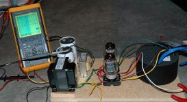
Here's my KT88 push-pull output stage "breadboard" with Plitron CFB specialist OPT.
Power transformer is Hammond 270HX through diodes and pi filter with two electrolytics and a Hammond choke for 400VDC.
I'm driving the grids with a Lundahl interstage transformer as a phase-splitter.
How does it sound? Don't know yet. I'm lucky to have the time to get it working, not even doing critical listening!
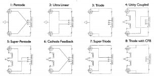
Plitron has some fascinating configurations using their push-pull specialist transformers. My KT88 amp will be switchable between 5,7, and 8. Configurations 7 and 8 are traditional. I'm wondering how 5 will sound.
Power transformer is Hammond 270HX through diodes and pi filter with two electrolytics and a Hammond choke for 400VDC.
I'm driving the grids with a Lundahl interstage transformer as a phase-splitter.
How does it sound? Don't know yet. I'm lucky to have the time to get it working, not even doing critical listening!
Plitron has some fascinating configurations using their push-pull specialist transformers. My KT88 amp will be switchable between 5,7, and 8. Configurations 7 and 8 are traditional. I'm wondering how 5 will sound.
Attachments
The UL feedback has to take into account the tube's g2/g1 Mu factor. So a pentode with a g2/g1 Mu of 10 say, would need 43% UL to equal 4.3% CFB. Combining both (using a fixed screen supply) with X% CFB would then also have X% UL but only X%/Mu additional effect in equivalent terms to the CFB (so X% + X%/Mu eff. CFB). (X being in terms of a fraction of total primary winding turns, C + P, for all cases here)
The argument is sound but .... way I look at it is that classic UL alters the tube's internal characteristics since it is inherent in the output topology; this is evident from graphs. Applying 'overall' NFB via g1 occurs 'outside' the tube, linearising whatever occurred inside. I have not fully investigated this, but a difference does show between the one and the other manner, using 'equal' degrees of NFB. Feedback via g1 (only) does not change the inherent pentode characteristics, only linearity. E.g. maximum available output remains the same before G1 current starts, but not in UL. But this becomes a little academic; not to confuse Kashmire.
Kashmire,
Interesting experiment ahead for you. You realise that not all comparisons would be 'apples to apples'; in some of those configurations you would be exchanging quality for maximum output, always a difficult choice. But I look forward to your findings!
- Status
- This old topic is closed. If you want to reopen this topic, contact a moderator using the "Report Post" button.
- Home
- Amplifiers
- Tubes / Valves
- Question - Output Trafo with CFB