Folks,
I've been playing with power supply filters in my 6LU8-based Spud lately. I'm using a 5AR4 rectifier and an Antek AN-1T250 transformer to deliver a B+ of 300-ish V. Actual B+ is 290 V for an AC line voltage of 115-120 V. The reservoir cap is 47 uF.
I would prefer not to drop too much voltage across the supply filter as that will limit the available output power. But I would like to have decent ripple rejection.
With an RC filter, I had quite audible 120 Hz hum on the output of the amp even with my 87 dB efficient speakers. It was audible from the listening position a good 2~2.5 meters away. I measured 28 mV RMS @ 120 Hz on the output.
I figured a choke would be a better option, so I got myself a 1.5 H Hammond choke from AES and rigged that instead of the resistor. That knocked the output hum down to 4~5 mV - which, amazingly, was still audible from the speakers.
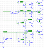
So, inspired by Pete Millett, I started looking at capacitance multiplier circuits. With a BJT, the base current sets the upper limit on the base resistor as it determines the base voltage, hence, the voltage drop across the cap multiplier. As I wanted to limit the capacitance on the base to 100 uF (keeping an eye on cost and parts availability here) that determined the lower end of the cutoff frequency for the ripple filter. Also, beta (ratio between collector and base current) tends to vary quite a bit with temperature, collector current, and - more importantly - part to part. For high-voltage BJT's beta also tends to be quite low. MOSFETs become really attractive at this point... So that's what I ended up with. With a voltage divider consisting of a 33 kOhm in series with a 1.35 MOhm (2M7 || 2M7), a 100 uF cap, and an 800 V NMOS, I get about 500 uV of hum on the output. I need to rig a spectrum analyzer to it, but it sounds like it has some 3rd order modulation products in it. I'm running the heaters on AC, so I'm guessing that I'm starting to see whatever ripple is left being modulated by the 60 Hz from the heater.
Sound quality... Aside from the hum, I also listened to some music at moderate volume. The amp with RC and LC filters sounded about the same. As the volume was turned up, OPT distortion came into play (I'm using Edcor XSE15-8-5K) and the bass became very muddy. But at more reasonable listening volumes (which is actually fairly loud) I found the amp quite laid back and melodic. It wasn't super accurate. The bass was firm but not tight. The highs were a bit fuzzy, which was a bit tiring. But aside from this, it's actually quite nice.
I got the MOS filter installed last night. With the MOS filter, the highs really open up! I was shocked! The bass was a bit firmer, but the main difference was the precision in the highs. It's not harsh and sterile like my sand amp (125 Wpc based on an LME49810), though, the final verdict on the sand amp is pending a little debugging to remove some hiss. The added imaging in the high end was certainly welcome. It's reasonably precise and laid back at the same time. The sound stage has opened up quite a bit as well.
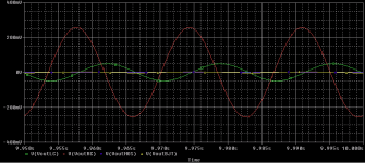
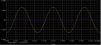
Anyway... To get to the point and subject of the thread. I ran some simulations of the different ripple filters to satisfy my curiosity. Specifically, I was wondering if there was any significant difference between the BJT and MOS cap multipliers. I used a 60 Hz 1 V peak sine wave to emulate the ripple. Of course, actual supply ripple is 120 Hz and isn't sine shaped at all, but I was looking for worst case and really just the differences between the different filter types. I suspect the differences in the sound quality has more to do with the output impedance of the supply, though. Well... Aside from the obvious attenuation of the 120 Hz hum that I was hunting in the first place.
I thought I'd share the results...
~Tom
I've been playing with power supply filters in my 6LU8-based Spud lately. I'm using a 5AR4 rectifier and an Antek AN-1T250 transformer to deliver a B+ of 300-ish V. Actual B+ is 290 V for an AC line voltage of 115-120 V. The reservoir cap is 47 uF.
I would prefer not to drop too much voltage across the supply filter as that will limit the available output power. But I would like to have decent ripple rejection.
With an RC filter, I had quite audible 120 Hz hum on the output of the amp even with my 87 dB efficient speakers. It was audible from the listening position a good 2~2.5 meters away. I measured 28 mV RMS @ 120 Hz on the output.
I figured a choke would be a better option, so I got myself a 1.5 H Hammond choke from AES and rigged that instead of the resistor. That knocked the output hum down to 4~5 mV - which, amazingly, was still audible from the speakers.
So, inspired by Pete Millett, I started looking at capacitance multiplier circuits. With a BJT, the base current sets the upper limit on the base resistor as it determines the base voltage, hence, the voltage drop across the cap multiplier. As I wanted to limit the capacitance on the base to 100 uF (keeping an eye on cost and parts availability here) that determined the lower end of the cutoff frequency for the ripple filter. Also, beta (ratio between collector and base current) tends to vary quite a bit with temperature, collector current, and - more importantly - part to part. For high-voltage BJT's beta also tends to be quite low. MOSFETs become really attractive at this point... So that's what I ended up with. With a voltage divider consisting of a 33 kOhm in series with a 1.35 MOhm (2M7 || 2M7), a 100 uF cap, and an 800 V NMOS, I get about 500 uV of hum on the output. I need to rig a spectrum analyzer to it, but it sounds like it has some 3rd order modulation products in it. I'm running the heaters on AC, so I'm guessing that I'm starting to see whatever ripple is left being modulated by the 60 Hz from the heater.
Sound quality... Aside from the hum, I also listened to some music at moderate volume. The amp with RC and LC filters sounded about the same. As the volume was turned up, OPT distortion came into play (I'm using Edcor XSE15-8-5K) and the bass became very muddy. But at more reasonable listening volumes (which is actually fairly loud) I found the amp quite laid back and melodic. It wasn't super accurate. The bass was firm but not tight. The highs were a bit fuzzy, which was a bit tiring. But aside from this, it's actually quite nice.
I got the MOS filter installed last night. With the MOS filter, the highs really open up! I was shocked! The bass was a bit firmer, but the main difference was the precision in the highs. It's not harsh and sterile like my sand amp (125 Wpc based on an LME49810), though, the final verdict on the sand amp is pending a little debugging to remove some hiss. The added imaging in the high end was certainly welcome. It's reasonably precise and laid back at the same time. The sound stage has opened up quite a bit as well.
Anyway... To get to the point and subject of the thread. I ran some simulations of the different ripple filters to satisfy my curiosity. Specifically, I was wondering if there was any significant difference between the BJT and MOS cap multipliers. I used a 60 Hz 1 V peak sine wave to emulate the ripple. Of course, actual supply ripple is 120 Hz and isn't sine shaped at all, but I was looking for worst case and really just the differences between the different filter types. I suspect the differences in the sound quality has more to do with the output impedance of the supply, though. Well... Aside from the obvious attenuation of the 120 Hz hum that I was hunting in the first place.
I thought I'd share the results...
~Tom
Attachments
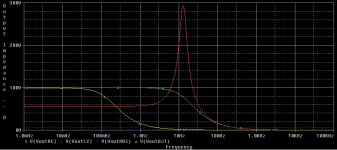
...and output impedance plot. The fact that the BJT and RC both have 100R Zout at LF is purely incidental. The NPN beta happens to be just shy of 100, hence, the output impedance becomes 10k/100 = 100R. It is interesting to note that the output impedance of the MOS follower is constant with frequency (for the simplistic SPICE model anyway). Another benefit of no base current, I guess... I'm not normally a fan of MOS, but in this case I guess I have to accept its superiority.
~Tom
~Tom
Attachments
")
- Status
- This old topic is closed. If you want to reopen this topic, contact a moderator using the "Report Post" button.