Hi everybody!
Well, I think that I'm definitely a medium / low watt Push-Pull supporter. Really deeeply like all those amps like El Cheapo, Baby Huey, RLD, Frankenhouse and the genre.
Even if maybe in the future I'll able to put together one of my own design, sure it will be of a similar topology.
So I'm thinking about to develop some kind of standard chassis and layout that can accomodate this type of amplifier.
The picture shows a very preliminar effort, but I'd like some advise, letting aside the asthetics, in regard the convenience of the showed phisical disposition of parts.
Many tanks
JJT
Attachments
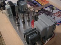
Generally it's best to have the power magnetics as far from the signal magnetics as possible. I can't really tell if you've done that there, but I'd do something like power magnetics (shared) in the center, with OPTs and other signal magnetics on the edges with the tubes in between. That being said, it looks like the rotation of the transformers *should* prevent coupling. I believe it is somewhat transformer dependent as to how close they can get before coupling. Pointy's steel mesh shield sounds like a good idea, but I am not familiar with the aformentioned tea trolley ") ! I know we like to see our tubes, but taking a hint from RF equipment, I am surprised more high quality amps don't have preamps, power stages, and magnetics in closed, divided steel compartments.
! I know we like to see our tubes, but taking a hint from RF equipment, I am surprised more high quality amps don't have preamps, power stages, and magnetics in closed, divided steel compartments.
! I know we like to see our tubes, but taking a hint from RF equipment, I am surprised more high quality amps don't have preamps, power stages, and magnetics in closed, divided steel compartments.Yes, it's painted with aluminium primer, cause I don'like the original glossy finished metal bells.
I'll finish the OPTs same way.The product is a german made coat.
Duplicolor
Motip Dupli GmbH
Hassmersheim
product code 557255
If you are based in Madrid, you'll found it at Leroy Merlin stores.
PD: Pointy, I'm sorry it seems that I'm not in one of my smart days, of course the name is "Radford" not Ratford..
Last edited:
Morgan Jones gives good advice on this in "Building Valve Amplifiers". In summary, I believe what he says is that you try to keep the small signals away from the big currents and magnetic fields. To that end your amp would be (from front to back) small signal tubes, output tubes, output transformers, rectifier tube and then the power transformer and choke at the back of the chassis. The way you have it laid out now, you are going to have to have high voltage lines going from your power supply past your input tubes to the output transformers.
Layout is more than just the interaction of the magnetics. Think about the voltage and current of all the wiring and how it will interact with the signal.
Also, don't forget about the heater wiring - tightly twisted right up to the sockets and tucked in to the chassis corners etc.
Regards,
Chris
Layout is more than just the interaction of the magnetics. Think about the voltage and current of all the wiring and how it will interact with the signal.
Also, don't forget about the heater wiring - tightly twisted right up to the sockets and tucked in to the chassis corners etc.
Regards,
Chris
The amp would look better if the two OT are facing the same direction. Don´t expect hum problems because of this.
Hi! I'll try this in the bredboard, if no issues appear, it can be done...
Last edited:
Layout is more than just the interaction of the magnetics. Think about the voltage and current of all the wiring and how it will interact with the signal.
Well, I've got some constraints here. The 9" by 18" chassis is what it is...
But You're right, it will be worthy to carefully check Morgan Jones on the topic
.. Thanks!
Last edited:
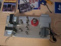
In your second photo, I would move the input and output tubes all the way to the left (as viewed) of the chassis, that is, all the way to the front. Place the output transformers where your output tubes now are.
This way you will have a short run of B+ to output transformers. Short run of wires from output transformers to output tubes. No high voltage/high current wiring close to input tubes. If you are going to wire a mains switch to the front panel, I would run this down one side of the chassis with the heater wiring. Run the input wiring (if using RCA jacks on back panel) down the other side of the chassis. Think carefully about grounding. This article on grounding is what switched the lights on for me Star Grounding although I personally use a ground bus. It is important here to understand where the currents are, and keep the large currents away from the low level input signal.
Cheers,
Chris
I see that you have "Valve Amplifiers" by Jones, but it is in the companion book "Building Valve Amplifiers" that he talks about chassis layout and wiring. Well worth the purchase.
I see that you have "Valve Amplifiers" by Jones, but it is in the companion book "Building Valve Amplifiers" that he talks about chassis layout and wiring. Well worth the purchase.
Lucky me , I own a copy of this one too!
As for your suggestions, I will try the new element disposition and then, shot a photo.
My first approach was to put the fused IEC mains connector, with integrated switch on a side of the wooden frame (plywood), near to the mains transformer.
RCA inputs on the alluminium plate, in some convenient place near the input tubes, and a short run of shielded cable.
Speaker binding posts (banana plug) on top plate too.
I was thinking on a copper rod as ground bus inside , all along the chassis.
Last edited:

omg - you are NOT going to use wood are you?
lol
Like it - my new amp will be running the power magnetics in the middle of the chassis with the two signal circuits at opposite ends.
Another classic layout is power at one end, signal at the other. Its all a balance of aesthetics, space and operation, you end up compromising something!
lol
Like it - my new amp will be running the power magnetics in the middle of the chassis with the two signal circuits at opposite ends.
Another classic layout is power at one end, signal at the other. Its all a balance of aesthetics, space and operation, you end up compromising something!
Wood it is. But only cause no one that I can access in the neighborhood is able to bend alluminium or metal sheets In any case I take care to give a look Ikea modern style rather than a Granma oldradio fat one
I say Ikea because to referring to Alvar Aalto by long exceeds my design skills
In any case I take care to give a look Ikea modern style rather than a Granma oldradio fat one I say Ikea because to referring to Alvar Aalto by long exceeds my design skills

yep. Like you had at first, but with the opts facing the same way as each other. There are so many variations and there is no "One True Design"
My last power amp build had power magnetics down the right side, signal magnetics at the rear on the left side, all under the chassis (flat aluminium panel), drive and control electronics on a PCB fitted to the inside of the rear panel, tubes above where I can see them!
My last power amp build had power magnetics down the right side, signal magnetics at the rear on the left side, all under the chassis (flat aluminium panel), drive and control electronics on a PCB fitted to the inside of the rear panel, tubes above where I can see them!
- Status
- This old topic is closed. If you want to reopen this topic, contact a moderator using the "Report Post" button.
- Home
- Amplifiers
- Tubes / Valves
- Chassis Layout Advice