Take a look at the "DAC-to-ADC" vs. DAC-to-SoundCardInterface-to-ADC" graph.
I'm inclined to say: not bad for diy. Definitely a worthy effort. Thank you, Pete.
Hello grufti, I do not understand the experiment setup. Could you please expand on it a bit?
gr. Mouser seemed to manage to damage U6 (couldn't even straighten the legs out). Can I power it up with everything else populated?
Sure, no problems.
Can anyone tell me what the normal current consumption of the converter happens to be?
Have not measured the input, but calculated about 50mA with the original parts from +/-15V = 1.5 watts. With converter efficiency tossed in I would expect about 350-400mA input at 5V.
I have not checked to see if the THAT parts draw comparable current to the TI/BB parts.
If the PTC is dropping some voltage, the input current will go up as well. Might want to verify the input voltage at the converter is really 5V.
Pete
This converter is pretty noisy too, I noticed spikes on the dc output of more than several hundred mV (it was late so I do not recall the period, but I believe it was few uS or so)
You do have low-ESR caps on the converter output, don't you? Generic electrolytics are useless here...
You do have low-ESR caps on the converter output, don't you? Generic electrolytics are useless here...
Absolutely..

Have not measured the input, but calculated about 50mA with the original parts from +/-15V = 1.5 watts. With converter efficiency tossed in I would expect about 350-400mA input at 5V.
I have not checked to see if the THAT parts draw comparable current to the TI/BB parts.
If the PTC is dropping some voltage, the input current will go up as well. Might want to verify the input voltage at the converter is really 5V.
Pete
Pete, it sounds like you are confirming what I suspected, I think the PTC I choose is a big part of the problem, I should probably have chosen one rated at amp or so. (The one you specified was out of stock, and the one I substituted was as close as I could find, but had slightly higher resistance.) It definitely seems load dependent, and I honestly expected the converter efficiency to be higher. I based the choice of the PTC on an worst case load current of 400mA or so. As the PTC heats up the voltage drops, current increases it heats further until the supply just collapses, and this will happen if the load current approaches 500mA. The nominal voltage is very close to 5.0V at the USB connector side of the PTC, and several hundred mV lower after the PTC with just 3 of the 5 ics installed. I think I will just remove the PTC until such a time as I can get the right one, but will check with an external current limited 5V supply to make sure nothing is amiss before plugging it back into the pc. (USB ports are inherently current limited at just a little over 500mA anyway.)
Edit: IIRC The ThatCorp parts draw a few extra mA at idle, but in my application this is an advantage because otherwise the load current on the switcher would be less than that required for proper regulation. (No meter ICs)
Last edited:
Well I found the cause of the excessive current draw, turned out to be a minor board level defect - an almost invisible trace between pins 6 (output) and pin 7 (+15V) of U6. A quick procedure with an x-acto knife and the current dropped right down to just a couple of hundred mA on the 5V supply. The IC which is a BB INA134AP seems to be ok. (Installing U6 or U1 resulted in an overloaded power supply due to this issue.)
I should be able to get the box up and running by tonight, (gotta go out shortly) provided that I do not have any blown chips. Will check for other related issues just in case.
The PTC apparently gets to stay for the time being. Using the bench supply during the quick troubleshooting exercise with the PTC circumvented the input supply current was about 800mA @ 5.00V which is really a bit beyond the supply's rating.
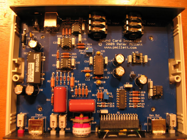
Happy to report I now have a nicely working sound card interface.
One of the minor improvements I made was the shield the bottom of the case with copper foil. (it's solderable) This helps with "proximity effect" aka electro-static coupling.. There does appear to be some sensitivity on the top side which is not shielded so I am going to add shielding there as well. The shielding is grounded to the "sound out" ground pins on the jack by a small piece of foil on the pcb that contacts foil on the adjacent stand-off.
One of the minor improvements I made was the shield the bottom of the case with copper foil. (it's solderable) This helps with "proximity effect" aka electro-static coupling.. There does appear to be some sensitivity on the top side which is not shielded so I am going to add shielding there as well. The shielding is grounded to the "sound out" ground pins on the jack by a small piece of foil on the pcb that contacts foil on the adjacent stand-off.
Well I found the cause of the excessive current draw, turned out to be a minor board level defect - an almost invisible trace between pins 6 (output) and pin 7 (+15V) of U6.
Was this an actual copper defect in the bare PCB? If so I need to complain to my vendor - these boards are supposed to be 100% tested!
Hello grufti, I do not understand the experiment setup. Could you please expand on it a bit?
The "DAC-to-ADC" graph is simply a THD+N graph of the DAC output going directly back to ADC input and then getting analyzed in AudioTester. This is the bottom graph.
Simultaneously the same 1000Hz signal is going from another channel of the same DAC into the SoundCardInterface out of the "Gen Out" right back into the SCI input and back out to the ADC input to get analyzed in AudioTester.
I did this at a signal level for the 1kHz signal just below 200mV rms at the SCI "Gen Out" output and in the 200mV setting of the SCI. The signal level at the DAC out is lower than that because there is a bit of amplification inside the SCI on the path from Input to Gen Out.
What you see in the top graph is THD+N of the SCI at these settings.
Was this an actual copper defect in the bare PCB? If so I need to complain to my vendor - these boards are supposed to be 100% tested!
Hi Pete,
Yes indeed it was a copper defect, one which when I looked closely was large enough to be noticeable, but I did not notice it.
I clean my boards with alcohol, but did not completely remove the remaining film which obscured the issue.This on reflection is something they should have caught on board probe - the resistance was < 1 ohm measured with the Keithley 2002 (not in Kelvin mode)..
Incidentally, IMHO this is a very nice board - one of the best I have seen for a kit based project.
Got my board and am slowly stuffing it as budget (tiny) permits. May be some time before I implement the meter display parts.
<snip>
Surplus Sales of Nebraska had nearly all the resistors I wanted in RN55E (25 ppm) or equivalent parts. They've got some high precision Vishay foil 50K resistors, which might be good for the input section; these are probably the lowest noise resistors available. I just don't like the idea of using these parts as possible fuses.
My original thought was to use a AC VTVM such as the Heathkit IM-5238 as a front end for a sound card analyzer, but it's just too noisy and distorted to use without major mods. With the Millett Meter (tm)
Those high precision resistors 50K foil types will buy you little or nothing over a good MF type in terms of noise performance, it is mostly determined by the Johnson noise (thermal noise) generated which is dependent on the value of the resistor and its temperature. Input current is minute with any of the recommended fet op-amps so bias currents flowing through the resistors will not add significant excess noise either. (Not that MF types in general are bad wrt this issue.) The resistors don't act as fuses either, basically they limit the input current to a few mA with a several hundred voltage overload which incidentally turns on the clamp diodes to the supply which are what keep the op-amps happily within an acceptable input voltage range. (Slightly above the supplies)
CMRR should be slightly helped if you can match the two 7.50K (R21 and R23) resistors closely. Mine are matched to better than 0.05%, however this is only true at the temperature I matched them at! Tempco is 100ppm/degree C so it will be slightly worse at any other temperature unless they actually track which given they are two separate resistors and not adjacent to each other is unlikely. Substitute a ground link for R24. These changes can improve the CMRR, and are easy to do.
I've always wanted an AP, and have used the 2722 in ATE qualification work (ac front end for an instrument in a semiconductor ATE test system). I would settle for a System One single or dual domain, but even these discontinued models sell for a hefty chunk of change on eBay and elsewhere. So this answers my needs too..
Last edited:
Those high precision resistors 50K foil types will buy you little or nothing over a good MF type in terms of noise performance
Ignoring noise, wouldn't closely matched resistors R2/R16 - say 0.1 % - improve CMRR? Since I can't get 50K 2 Watt resistors I was planning to parallel several smaller 0.6W MF resistors, which I can get with 0.1% fairly cheaply.
And a question re. input protection diodes D5-D8: 1N4148 have only 100V reverse voltage, is there not a small chance that they could break before the forward diode starts conducting, or conversely, would 1N4004 or similar do any harm, say by having too much capacitance?
The 1N4148 PIV is much higher than the input of those op-amps can tolerate, they start to conduct almost immediately when the VF across them exceeds their forward voltage which is ~ VS + 0.6V. There should never be more than ~16V at the input of the op-amp in the front end. The 1N4148 has relatively low capacitance, and a quick response. The 1N400x diode is a power rectifier - has considerably higher leakage and capacitance - not recommended here.
Neglecting for a moment the effect of the op-amp's input capacitance and that of the diodes, R2 and R16 have almost no effect on the CMRR, to make a meaningful improvement the diodes would have to be selected for low junction capacitance and the op-amp would have to be checked for differential and shunt input capacitance. So in short don't waste your time on these resistors. Capacitances and resistances at the input would have to be extremely well matched at the input, note also that the input circuit is not symmetrical - the idea was to achieve some hum rejection which is effective because the asymmetries are not that significant at low frequencies. (Note that the input capacitors are critical for match if you want good cmrr where it counts! Make sure they are well matched...)
Last edited:
Did you guys use the mounting clip that comes with the MDMV?
I didn't.
The "DAC-to-ADC" graph is simply a THD+N graph of the DAC output going directly back to ADC input and then getting analyzed in AudioTester. This is the bottom graph.
Simultaneously the same 1000Hz signal is going from another channel of the same DAC into the SoundCardInterface out of the "Gen Out" right back into the SCI input and back out to the ADC input to get analyzed in AudioTester.
I did this at a signal level for the 1kHz signal just below 200mV rms at the SCI "Gen Out" output and in the 200mV setting of the SCI. The signal level at the DAC out is lower than that because there is a bit of amplification inside the SCI on the path from Input to Gen Out.
What you see in the top graph is THD+N of the SCI at these settings.
Thank you for the explanation grufti. So the blue line plot is the SCI+soundcard and red line plot is the soundcard alone? If that's true, I would be worried because the blue plot seems to have more artifacts than the red plot, at 60Hz, 2kHz, and 3kHz. Also, have you in any way shifted the red plot lower or the blue plot higher, or this is how they came out of the analyzer? If you did not shift them, it would seem the soundcard alone has significantly lower noise floor. Did I get this wrong?
What soundcard is it, by the way?
Did you guys use the mounting clip that comes with the MDMV?
Nope, it doesn't fit in there. Another thing I should have mentioned
Luckily the fit is tight enough that it won't go anywhere.
Pete
Nope, it doesn't fit in there. Another thing I should have mentioned
Luckily the fit is tight enough that it won't go anywhere.
Pete
yup, I noticed, very tight fit!
well, things are almost ready to go!
- Home
- Design & Build
- Equipment & Tools
- Test & Measurement interface for Soundcard