I have not built it yet.
That's a good thing. The Walton-Cockroft is a bad choice for a voltage doubler. The W-C is half wave circuit, which means DC through the secondary. This is highly likely to cause core saturation. The W-C is useful when the current demand is much lower, and when you can use it with a gapped core xfmr (think CRT flyback xfmrs here). That should be replaced with a full wave doubler.
That's a good thing. The Walton-Cockroft is a bad choice for a voltage doubler. The W-C is half wave circuit, which means DC through the secondary. This is highly likely to cause core saturation. The W-C is useful when the current demand is much lower, and when you can use it with a gapped core xfmr (think CRT flyback xfmrs here). That should be replaced with a full wave doubler.
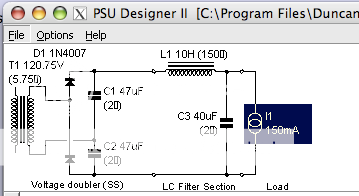
I don't understand it. To me the original schematic is based on a full wave doubler, at least it is exactly like this schema (last schema on the page)
but, if it is not, I can explain it by the fact that it is almost two in the morning
")
Could be, but I don't think so. It's nearly a cut and paste from PSUDII... Notice the ground connection, I don't see DC. But if Mr. Prower says its there it must be... please explain! The only place that DC could be dawn is off ground, not through the tranny, no? This is Greinacher topology not WC.
Last edited:
Don't you find the 6V6 too microphonic for an input tube?
I wouldn't know, I've never heard it
I spend most my time with DHT.Could be, but I don't think so. It's nearly a cut and paste from PSUDII... Notice the ground connection, I don't see DC. But if Mr. Prower says its there it must be... please explain!
A full wave doubler should look like this
An externally hosted image should be here but it was not working when we last tested it.
If that's how it works, then it'll be just fine. Don't use PSUD-II, as I do designs the old fashioned way: with a scientific calculator, and so am not familiar with the effffffffffffffff-up ways PSUD presents schemos.
That thing still looks like a W-C, and is very confuzzling.
Sorry Miles, I'm self taught and sometimes my schematics are from Mars I get that all the time! Your inquiry is very much appreciated! I'm glad there is no smoke (yet).
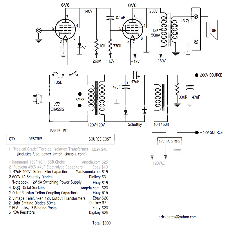
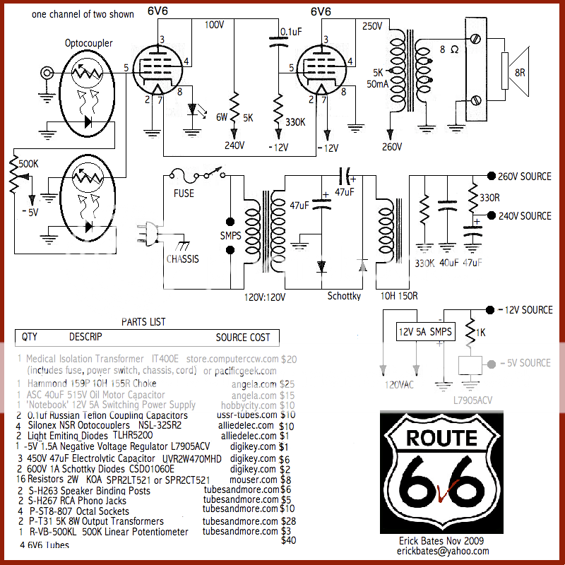
And happily, I have been able to source all the parts from NON-Ebay vendors, so its a go! And here is the updated schematic, still under $200!
Take a guess how it'll sound, I haven't a clue! I'm thinking maybe a little distortion cancellation of 6V6 driving 6V6 and stunning detail. If microphonics is a issue I'll adjust the driver circuit for a lower loading of 6K.
http://greenvalve.wordpress.com/files/2009/11/bates-200-6v6-amp-schematic.jpg?w=560
I get that all the time! Your inquiry is very much appreciated! I'm glad there is no smoke (yet).And happily, I have been able to source all the parts from NON-Ebay vendors, so its a go! And here is the updated schematic, still under $200!
Take a guess how it'll sound, I haven't a clue! I'm thinking maybe a little distortion cancellation of 6V6 driving 6V6 and stunning detail. If microphonics is a issue I'll adjust the driver circuit for a lower loading of 6K.
http://greenvalve.wordpress.com/files/2009/11/bates-200-6v6-amp-schematic.jpg?w=560
Last edited:
Those OPTs don't inspire confidence. I think I'd come up with the extra $4 each for some Edcors.
You are so right. I just can't decide what to give up. I may have to whack the 40uf oil cap and use an electrolytic. Its not fair.
I think its time to go back and add it all up to the penny.The 6V6's are $35.80, not $40, so there's one Edcor. Also, Triad chokes are cheaper than Hammonds Triad Magnetics - C-14X - Allied Electronics
Great idea. I'm going to sim the Triad chokes. How much ripple do you think 5K loaded 6V6 finals can take and still be silent? The Input tube is dead silent already.
Going from 10H (144mv) to 6H is 244mv.
What about 2 dare I say Triad C-40X ? But that would up the cost again and need another cap. Nope, at this current the low DCR supply has over 1V of ripple.
Going from 10H (144mv) to 6H is 244mv.
What about 2 dare I say Triad C-40X ? But that would up the cost again and need another cap. Nope, at this current the low DCR supply has over 1V of ripple.
Last edited:
How much ripple do you think 5K loaded 6V6 finals can take and still be silent? The Input tube is dead silent already.
I don't know, how about 0? Build a shunt regulator (search for Salas' design -- should work fine) and lose the rest of the PS.
Rectifier circuit is fine
The doubler circuit is full wave. Best to draw the circuit for each half cycle - only one of the diodes will be conducting and a diferent capacitor is charged for positive half cycle compared to negative half cycle. Load is placed across the series connection of capacitors.
Ciao, Tim
The doubler circuit is full wave. Best to draw the circuit for each half cycle - only one of the diodes will be conducting and a diferent capacitor is charged for positive half cycle compared to negative half cycle. Load is placed across the series connection of capacitors.
Ciao, Tim
The multiplier is half wave. I dont see it as being a problem. If you could find a center tapped tranny, much like a site transformer or an industrial one where the CT is grounded you could build a full wave Coockroft-Walton type doubler but it would need two stages and be worse for it. Its fine as it is.
- Status
- This old topic is closed. If you want to reopen this topic, contact a moderator using the "Report Post" button.
- Home
- Amplifiers
- Tubes / Valves
- $200 6V6 Amp