Hi,
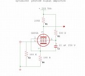
IME, R1 and R2 are too low... try R1 ~ 220K and R2 ~ 470K-1.5Meg. C1 is way too high, it'll take forever for the voltage to come up and the tube to begin emission. Try 0.1uF there.
6AU6 sonic characteristics are as wide and varied as the brand out there. Some hum, some are microphonic, some are brilliant full mids, some are flat as a transistor. You'll just have to "roll 'em"")
Cheers!
IME, R1 and R2 are too low... try R1 ~ 220K and R2 ~ 470K-1.5Meg. C1 is way too high, it'll take forever for the voltage to come up and the tube to begin emission. Try 0.1uF there.
6AU6 sonic characteristics are as wide and varied as the brand out there. Some hum, some are microphonic, some are brilliant full mids, some are flat as a transistor. You'll just have to "roll 'em"
Cheers!
Hi,
IME, R1 and R2 are too low... try R1 ~ 220K and R2 ~ 470K-1.5Meg. C1 is way too high, it'll take forever for the voltage to come up and the tube to begin emission. Try 0.1uF there.
Cheers!
hey-Hey!!!,
6AU6 runs ~30% of the plate current to the g2. With all pentodes, the load line is critically dependant on the g2 voltage. fortunately there is lots of the required data on various g2 voltage( as in plate current curve sets ). Choose the dropping R to the g2 in order to deliver your desired operating condition.
cheers,
Douglas
Heya Douglas,
That's why I said "IME", because I took several hours with a few on the breadboard tweaking them for best sound
That reminds me, this tube is covered under "Resistance Coupled Amplifiers" in the back of any RCA tube manual
Cheers!
That's why I said "IME", because I took several hours with a few on the breadboard tweaking them for best sound
fortunately there is lots of the required data on various g2 voltage( as in plate current curve sets ). Choose the dropping R to the g2 in order to deliver your desired operating condition.
That reminds me, this tube is covered under "Resistance Coupled Amplifiers" in the back of any RCA tube manual
Cheers!
Gregg,
Just looked at a schematic that had a 6AU6 as the input tube and it shows the same values that you mentioned. Is there a possibility of fudging the C1
value? I don't have any .1 at this time without ordering some but do have some .22 handy.
The values I have on my schematic are C1 .2, R1 221K, R2 1.5M R3 470K
Hey Mosquito,
Do you want your 6AU6 configured for max gain or lowest distortion and what undistorded outswing do you need if we are talking about the latter alternative?
Also Zin of next stage must be taken in account when finding the workingpoint.
Many variables but they must be known before final design of your circuit.
The Ua/Ia curves will be of help:
http://www.mif.pg.gda.pl/homepages/frank/sheets/093/6/6AU6A.pdf
Last edited:
Hi again. I much appreciate all your answers. I think the circuit (as seen) is optimized for minimun distortion. Gain is less important in my application. ( I guess is around 120/150, if i'm not wrong). In my intentions it is not for musical instrument, but for home fi.
Triodeel has some Telefunken not so cheap as for take a bunch to select...
Triodeel has some Telefunken not so cheap as for take a bunch to select...
Yes, in fact my idea is inspired in Shoog's design. I'll draw the whole stuff together, and then post it, to correction...
Many thanks
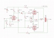
Dont copy Shoogs driver though. To work well the 6AU6 needs an Ua of at least 150V and a Ia of ca 10mA to work acceptable. A anoderesistors wont do either, with low voltage B+. So a voltage-controlled gyrator will be needed.
Do you have a real OPT or will you use a mains toroid? If using a toroid, a servo is the best. You can find it, designed by Rod C., in my Spud hybrid PP ECL86 thread. But everything will be much simpler with an OPT as only one CCS will be needed. A discrete MOSFET CCS will be best.
Last edited:
At the moment all I can say is that OPTs will be real PP transformers of medium to high quality, like Edcor or Hammond units. The Power transf. is custom made, with double 6.3 Volt/3A windings for the hungry 6Y6 heaters.
As a beginner that I am, sure I can go wrong about everything, but I'll prefer not to use CCSs, mirrors or sinks, if not strictly necessary..(all those fruity things, like someone else named them in this same forum)
As a beginner that I am, sure I can go wrong about everything, but I'll prefer not to use CCSs, mirrors or sinks, if not strictly necessary..(all those fruity things, like someone else named them in this same forum)
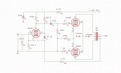
Well, I will try if something like this can work half decently
I'll order the 6AU6s from triode electronics
That's not gonna work unless you put a CCS under the 6Y6 cathodes.
Thanks a lot Miles and Lars
Ok, I'm pretty sure you're right, and at the end I will surrender to the crude facts and place the holy CCS.
But just to rescue me from the ignorance, what I'm missing in my drawing that make the Firefly or the Leibowitz amp to work without CCSs?
Regards
JJ
Ok, I'm pretty sure you're right, and at the end I will surrender to the crude facts and place the holy CCS.
But just to rescue me from the ignorance, what I'm missing in my drawing that make the Firefly or the Leibowitz amp to work without CCSs?
Regards
JJ
that make the Firefly or the Leibowitz amp to work without CCSs?
In your drawing there is a cathode-cap shorting the signal to tube 2.
About the examples above they work, but who said they work well
?To make a LTP do what it should, the tail must be of high impedance.
- Status
- This old topic is closed. If you want to reopen this topic, contact a moderator using the "Report Post" button.
- Home
- Amplifiers
- Tubes / Valves
- About the 6AU6s