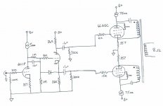
So I had an idea the other day while looking at parafeed designs and reading the thread on using power toroids as OPTs. I've got a pretty big junk box an have been looking for a project to clear alot out of it. Starting with a standard Williamson style front end - plate follower with split load phase splitter, nothing exciting here. Then a 6L6GC in parafeed with a CCS. I figured I'd add a second output tube in paralell, but a dual primary power toroid would give me a little more flexibility in wiring. I was thinking that running the tubes and transformer windings in opposite phases from each other would help with overall linearity. Has anyone tried something like this or see any pitfalls? I'm thinking it still has overall low power output compared to a P-P amp. If there's a major problem, I'd just go with a more standard P-P arrangement, but I figure I'd ask the experts first. Thanks.
PS. - B+ of around 360v.
PS. - B+ of around 360v.
Attachments
Last edited:
It will sound like P-P. Some possible advantage as far as PSRR, since the primaries are ground referenced instead of B+ reference. And the xfmr will be DC balanced. But those CCS's on the outputs are going to burn up power. And the output tubes have to run in class A too. I think this may be close to summing the disadvantages of SE parafeed with the disadvantages of P-P.
I think the caps to the primaries could be dispensed with if the primaries are just series connected between the plates. And the CCS's could be dispensed with by using a separate center tapped inductor to B+. But then it loses the PSRR advantage. Although P-P largely cancels out the Power Supply effects to first order anyway.
I think the caps to the primaries could be dispensed with if the primaries are just series connected between the plates. And the CCS's could be dispensed with by using a separate center tapped inductor to B+. But then it loses the PSRR advantage. Although P-P largely cancels out the Power Supply effects to first order anyway.
Last edited:
Power transformers are not designed to work past 60Hz.
Toroids work just fine. That's why they shouldn't be used in power supplies.
Toroids work just fine. That's why they shouldn't be used in power supplies.
")
You are using a power transformer for output? ..... Power transformers are not designed to work past 60Hz.
They rock in guitar amps though
Cheers!
http://www.anc-tv.ne.jp/~suzuki3/amp_6sl7_300bpp_rofchin/k_6SL7_300Bpp_Amp.pdf
This schematic will be of your interest. You can find it on a Japanese DIYer's website. As the website says in Japanese (sorry), the original design of this SE-PP switchable class-A 300b amp was actually published by Mr. Takaaki Uzike (or Ujike) in a couple of issues of RADIO GIJYUTSU magazine (a monthly Japanese DIY magazine like MJ) in 2000. In the articles, he says he developed the circuit and assembled his 300b amp, in order to make the best use of Permalloy PP output transformers, and named this output stage configuration "floating OPT", which I think is equivalent to "parafeed PP". Mr. Uzike used a pair of Tango NY-45-5 (discontinued).
Yoshi
Very cool. Thanks for the link. I don't for a second expect a 6SL7 running @1mA to be able to drive a 300B but this is a separate issue.
Why do people insist on putting fruity things in the plate circuit, where they do absolutely nothing? The only thing supplying it with a CCS will do is make it fart.
Besides, move some things around (which according to Kirchoff, is allowable, despite what some more imaginative posters might believe), and you get PP again. If you must have class A guaranteed, you can put a CCS in the cathode circuit, where it will have mu times more effect than in the plate circuit. (Not that that's a good idea anyway, it still makes it fart more when driven into clipping. At least it farts due to cathode drive instead of running out of supply voltage.)
Oh, and what's the diode for? Looks like an excellent source of nasty harsh silicon clipping. Not that it will do much as a triode's grid is a better diode than a 1N4007 anyway. And the voltage divider, you don't need that for a cathodyne, just bias the first stage correctly in the first place.
Tim
Toroids as OTs
Here is a recent thread - I started ...
http://www.diyaudio.com/forums/tubes-valves/153774-using-toroidal-pts-tube-ots-methods-sources.html
This concept of using a toroidal really interests me as OPTS are not available where I live. Can you give me some more details of the specs of the toroids I need in general?
Here is a recent thread - I started ...
http://www.diyaudio.com/forums/tubes-valves/153774-using-toroidal-pts-tube-ots-methods-sources.html
Oh, and what's the diode for? Looks like an excellent source of nasty harsh silicon clipping. Not that it will do much as a triode's grid is a better diode than a 1N4007 anyway. And the voltage divider, you don't need that for a cathodyne, just bias the first stage correctly in the first place.
Tim
The diode protects the tubes at turn-on, when the cathodes are cold and not conducting. Just a bit of cheap insurance. It stops being seen by the circuit once the tubes start conducting. The voltage divider is there because it sets the DC operating point of the phase splitter while keeping the anode and cathode resistors the same, allowing for the most linear and symetrical operation of the phase splitter.
I'm a sand-guy so forgive me if I'm missing something here. If the primary windings were ground referenced rather than cathode referenced wouldn't this be equivalent to a PP output, assuming zero PSU impedance?
Standard PP works with the transformer in series with the tubes. In this instance the transformer is in paralell with the tubes. The disadvantage is a lower voltage swing and the need for a CCS in the plate (which is more difficult than in the cathode because of the higher voltages). But the output current doesn't flow through the cathode resistor. If the transformer were ground connected (and hence connected together), both the signal and output currents would flow through the cathode resistors, but this way they stay separate. A minor philosophical difference.
The diode protects the tubes at turn-on, when the cathodes are cold and not conducting.
Protected from what?
It stops being seen by the circuit once the tubes start conducting.
Ah, but not completely. Reverse biased diodes are crappy capacitors. Probably not noticable in the audio range, but it'll do strange things in the cutoff region (changing the slew rate with respect to loading).
The voltage divider is there because it sets the DC operating point of the phase splitter while keeping the anode and cathode resistors the same, allowing for the most linear and symetrical operation of the phase splitter.
Ah, but the phase splitter itself is always biased at 1/4 V+ anyway, it has to be. If anything the excuse would be on the preamp stage, but it's actually more linear at lower voltages (further from cutoff). You just have to be sure to use a loadline that drops nice and low. Pentodes are good for this (also giving excellent gain, needed if you're applying GNFB), but regular triodes will also do well, as long as the plate resistor is big.
Tim
Fenris,
Nothing strange with your circuit. It´s been done before. This is an example of a preamp:
Figure 18
Check it and see that the primary windings shouldn´t be returned to ground, instead to each other to get a better PP function. Minor adjustment!
Maybe this could interest you too:
http://www.nutshellhifi.com/library/Tube_Fest_Talk.html
Last edited:

- Status
- This old topic is closed. If you want to reopen this topic, contact a moderator using the "Report Post" button.
- Home
- Amplifiers
- Tubes / Valves
- Strange idea for an output stage - comments requested