Hi all,
I am planning to build a tube buffer stage for my inverted gainclone.
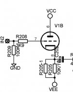
Then that design looked me so simple to build. I have some Russian 6N6P triodes in my drawer. Vcc=Vee=+/-35v regulated. Bias will be ~3,5mA.
My quesitons are;
- Does this design work good with my 6N6P?
- Is it a bad idea to supply that buffer with the same psu as gainclone?
- I am planning to use a simple 6v SMPS (35KHz) for the heaters! Does it make any noise?
Thanks in advance for your replies..,
I am planning to build a tube buffer stage for my inverted gainclone.
Then that design looked me so simple to build. I have some Russian 6N6P triodes in my drawer. Vcc=Vee=+/-35v regulated. Bias will be ~3,5mA.
My quesitons are;
- Does this design work good with my 6N6P?
- Is it a bad idea to supply that buffer with the same psu as gainclone?
- I am planning to use a simple 6v SMPS (35KHz) for the heaters! Does it make any noise?
Thanks in advance for your replies..,
Attachments
I am planning to build a tube buffer stage for my inverted gainclone.
OK ... why ? The answer to your next question depends on that.
- Does this design work good with my 6N6P?
See above and define "work"
") Abovementioned double triode isn't meant for preamplifier duty but it should work OK as a cathode follower. However I don't think you need a cathode follower there, you're going to drive an extrenmely high Z input. If you want a tube inbetween because you want it to add distortion ("tube sound") to your sound, you ought to consider some other topology - say simple voltage amplifier stage. Now comes the part where the answer depends on your reply to my question above ...
Abovementioned double triode isn't meant for preamplifier duty but it should work OK as a cathode follower. However I don't think you need a cathode follower there, you're going to drive an extrenmely high Z input. If you want a tube inbetween because you want it to add distortion ("tube sound") to your sound, you ought to consider some other topology - say simple voltage amplifier stage. Now comes the part where the answer depends on your reply to my question above ...- Is it a bad idea to supply that buffer with the same psu as gainclone?
If your PSU is powerful enough (low enough source Z), then no. If it isn't (so your buffer stage will drag PSU's rails around), then yes. Probably not though.
- I am planning to use a simple 6v SMPS (35KHz) for the heaters! Does it make any noise?
Can you hear 35 KHz noise ? I can't. I'd go for conventional transformer though simply because I can (6V 5 VA PCB transformers cost a couple of euros at your nearest electronics parts store and "just work" out of the box, no tweaking, no touchy sandy elements, etc.).
It really all boils down to "Why ?". Elaborate and you're bound to get more useful tips from the regulars.
I've been using 12AU7 cathode follower (unitary gain) to 2 months in my GAINCLONE LM3886, the buffer and the well semalhante Yaqin CD1 .
improved + - 20% the quality of my GAINCLONE, highly recommend you use a cathode follower tube in his GAINCLONE ok?
soon I will put here in the forum .... more details

. improved + - 20% the quality of my GAINCLONE, highly recommend you use a cathode follower tube in his GAINCLONE ok?
soon I will put here in the forum .... more details
An externally hosted image should be here but it was not working when we last tested it.
An externally hosted image should be here but it was not working when we last tested it.
OK ... why ? The answer to your next question depends on that.
See above and define "work"
If your PSU is powerful enough (low enough source Z), then no. If it isn't (so your buffer stage will drag PSU's rails around), then yes. Probably not though.
Can you hear 35 KHz noise ? I can't. I'd go for conventional transformer though simply because I can (6V 5 VA PCB transformers cost a couple of euros at your nearest electronics parts store and "just work" out of the box, no tweaking, no touchy sandy elements, etc.).
It really all boils down to "Why ?". Elaborate and you're bound to get more useful tips from the regulars.
Dear Arnulf,
Thanks for the reply first.
Why I want to make a tube buffer for my gainclone? There are some reasons of course;
- It sounds a bit (a lot in fact) bright and it gets boring after a while! I have a lot of gainclone type or discrete solid state amplifiers. However they sounded more or less the same! Ok I want to hear details but not sleep after half an hour.. If you ask "how do you know if you add a tube before it then it sounds get more balanced?", I dont know but as my experiences (and as some others say) with JFET input stages it must be!
- Inverted gainclones have low input Z, so hard to drive.
What do you mean with "other topology"? Its enoughly simple, class A and unity gain which I need. May you explain a bit more pls?
My PSU is regulated (2 x LT1083) and have a 225VA transformer with huge low ESR filter capacitors... However I am not experienced on tube circuits so I was not sure about that.
And for the heaters, I already have a huge transformer inside of the enclosure. So I dont want to add another (even if its tiny) one. As I heard, supplying the heaters with AC causes some mains noise on the sound. Then I would need rectifiers, big caps and regulators another cap etc to reduce possible noise. But I already have a 6v 1,5A and a really tiny SMPS in my drawer waiting for over 5 years... I want to be sure that causes any extra noise that I cannot imagine with my limited tube knowledge..
Thanks again.
- Inverted gainclones have low input Z, so hard to drive.
I had to Google for "inverted Gainclone" and I came across this page which details your idea
I wasn't quite sure what an "inverted" amplifier would look like.What do you mean with "other topology"? Its enoughly simple, class A and unity gain which I need. May you explain a bit more pls?
You can connect a single tube in three basic configurations. If I wanted more distortion to be added to the sound, I would have opted for common cathode topology, decrease the gain of the power stage to account for voltage gain in tube. If I wanted next to no effect I would have chosen cathode follower (or solid state unity gain buffer). Hence "Why ?" in my previous message.
6N6P is fairly non-linear at low currents so there would be plenty of distortion added this way
My PSU is regulated (2 x LT1083) and have a 225VA transformer with huge low ESR filter capacitors... However I am not experienced on tube circuits so I was not sure about that.
There is really no substitute for practical testing. I cannot hear 35 KHz. That doesn't mean it will not produce some kind of intermodulation product within your hearing range once you set up your circuit.
As I heard, supplying the heaters with AC causes some mains noise on the sound.
Theory goes like this: in indirectly heated tubes you can run the heater off of AC. If heater-to-cathode voltage is low (heater at lower potential), you have a (parasitic) vacuum diode between heater and cathode. Diode will rectify heater AC supply and inject this noise into the cathode. This is why it might be a good idea to elevate your heater supply so diode is always reverse biased and doesn't conduct.
In reality I have more mains noise in the rest of the circuit (which functions as an antenna) so I cannot distinguish it from heater noise (if there is any), plus it is only audible when I put my head directly onto the speaker (= a bad idea if music started to play all of a sudden) which I don't do very often. YMMV.
Then I would need rectifiers, big caps and regulators another cap etc to reduce possible noise. But I already have a 6v 1,5A and a really tiny SMPS in my drawer waiting for over 5 years... I want to be sure that causes any extra noise that I cannot imagine with my limited tube knowledge..
Point taken regarding the avaliability of PSU.
By all means do test your circuit. I wouldn't use 6N6P (I'd go for 6N1P instead), I would go for considerably larger grid stopper (at least 10K instead of 3.9K), I wouldn't complicate my life with SMPS heater supply, I wouldn't use cathode follower topology to drive a mid-lowish input Z solid state stage but I am not you - you might end up liking your result very much and IMO if you like the result, screw the theory and what the rest of us think
There is nothing wrong with your idea from technical point of view so it's just a matter of whether you like the outcome or not and only you can be the judge of that.
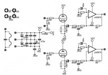
link with a good hybrid design gainclone
1.000.000 de Circuitos Eletrônicos Audio: hybrid LM3886 gainclone pre tube
1.000.000 de Circuitos Eletrônicos Audio: hybrid LM3886 gainclone pre tube
I had to Google for "inverted Gainclone" and I came across this page which details your idea
You can connect a single tube in three basic configurations. If I wanted more distortion to be added to the sound, I would have opted for common cathode topology, decrease the gain of the power stage to account for voltage gain in tube. If I wanted next to no effect I would have chosen cathode follower (or solid state unity gain buffer). Hence "Why ?" in my previous message.
6N6P is fairly non-linear at low currents so there would be plenty of distortion added this way
There is really no substitute for practical testing. I cannot hear 35 KHz. That doesn't mean it will not produce some kind of intermodulation product within your hearing range once you set up your circuit.
Theory goes like this: in indirectly heated tubes you can run the heater off of AC. If heater-to-cathode voltage is low (heater at lower potential), you have a (parasitic) vacuum diode between heater and cathode. Diode will rectify heater AC supply and inject this noise into the cathode. This is why it might be a good idea to elevate your heater supply so diode is always reverse biased and doesn't conduct.
In reality I have more mains noise in the rest of the circuit (which functions as an antenna) so I cannot distinguish it from heater noise (if there is any), plus it is only audible when I put my head directly onto the speaker (= a bad idea if music started to play all of a sudden) which I don't do very often. YMMV.
Point taken regarding the avaliability of PSU.
By all means do test your circuit. I wouldn't use 6N6P (I'd go for 6N1P instead), I would go for considerably larger grid stopper (at least 10K instead of 3.9K), I wouldn't complicate my life with SMPS heater supply, I wouldn't use cathode follower topology to drive a mid-lowish input Z solid state stage but I am not you - you might end up liking your result very much and IMO if you like the result, screw the theory and what the rest of us think
There is nothing wrong with your idea from technical point of view so it's just a matter of whether you like the outcome or not and only you can be the judge of that.
Hmmm...
What about to increase the buffer stages bias current? Currently its about 3,5mA.. So what if I increase it to; say 10mA or more? More current noise?
Or what do you mean with "non-lineer at lower currents"? Is it non-lineer frequency response in audio range? If so what kind of problems I will face do you think?
And concerning the grid stopper; I am not sure about that resistor.. Does it really work? Mean, if theorically the grid sinks 0 current from the source, whats the meaning of that resistor?
Thanks again...
link with a good hybrid design gainclone
1.000.000 de Circuitos Eletrônicos Audio: hybrid LM3886 gainclone pre tube
In fact, at the beginning
I was thinking about to build this one. However I coulndt understand its feedback topology! So my philsophy is,
"the right way is which you can understand"
Then I switched to a "normal" inverted clone + "normal" cathode follower buffer.
Do you think its better than mine?
Or what do you mean with "non-lineer at lower currents"? Is it non-lineer frequency response in audio range? If so what kind of problems I will face do you think?
As I said above: I would go for a common cathode stage but that's just me. A common cathode 6N6P stage is fairly non-linear at 3.5 mA quiescent current (check out the datasheet and compare it with common pre-amplifier tubes - the dynamic characteristics curve).
This is irrelevant with cathode follower.
And concerning the grid stopper; I am not sure about that resistor.. Does it really work? Mean, if theorically the grid sinks 0 current from the source, whats the meaning of that resistor?
Thing is .... you can't purchase ideal (theoretical) triodes
They all have some input capacitance and even though you avoid Miller effect with cathode follower stage, its input capacitance is still higher than zero (a couple of pF actually) and consequently represents a lower-than-infinite impedance for AC signals. This isn't necessarily a bad thing though; combined with grid stopper the input capacitance can be made to work to your advantage, eliminating RF noise (MW and up) that your circuit would otherwise inevitably pick up. You have to make sure that the filter you create this way doesn't cut off anything without audible frequency range but that's hardly a problem.
Your current choice of grid stopper (combined with input capacitance) provides for a very high cut-off point (well into SW range) and therefore doesn't take of any potential MW interference (such as AM radio). I would go for larger grid stopper as you're still waaaaay (more than two decades) from AF range.
I wouldn't waste time doing precise calculations. I would put 10K or more (whichever value I came across first) there for starters and increase it if I noticed any problems while listening to it; if you plan your element placement accordingly you can swap it with more suitable value later. Just make sure you put it as close to the grid pin as possible to gather as little inductance along with the trace as possible.
Hi all,
I have a confusing about the heater supply that;
Should I connect heater voltages (-) pol to amplifiers GND?
I have seen a lot of tube schematics on the net and some of them was connected to GND and some others not..
So is there any relation between heater and cathode (or any other pin of tube)???
Thanks in advance for your replies..
Hi,
Finally finished and made a listening test with my KEF Q1 last weekend.
First, the sound was noticeable improved, compared to the "nude" LM3875gainclone. It has warmer and more balanced sound. Especially the mids were more open and can be described as articulative. The soundstage was more wider compared to the nude one. Vocals, pianos, strings were very clear and not bright.
However the tube buffered amplifier can not be described as "fast" as the other one. But "more musical" as a final word.
So I like it too much.
But I have a problem with noise. I hear 100Hz noise that hearable from one meters long. My power supply is regulated (with 2 x LT1083) +/-35v and I did not hear anykind of noise with "nude" gainclone and SE JFET buffered one with the same supply.
I am using the same rails with the LM3875. Can you help me to reduce the noise pls? This is my application;
Attachments
How is your heater supply for the 6n6p referenced to earth?I hear 100Hz noise that hearable from one meters long.
Yes this is "the meaning of life" question!
I have asked a lot of times that but have no answer as you can see. Because I dont know anything the relation between cathode and heater voltages! So my heater is independent from the suppy rails. Its about 6,5v and regulated (LM317)... But when I feed it with AC the noise was louder..
I have asked a lot of times that but have no answer as you can see. Because I dont know anything the relation between cathode and heater voltages! So my heater is independent from the suppy rails. Its about 6,5v and regulated (LM317)... But when I feed it with AC the noise was louder..
AC should be quiet enough. With AC you should ground the center tap of your heater transformer. If you don't have a center tap. Create one with two 100R resistors from each "leg" to ground.
Do the same with the DC supply. From the positive leg add one 100R resistor and on the negative leg one 100R resistor. Connect the other ends of the 100R resistors to each other. And connect that to ground or the cathode. (Try both to see which is quieter)
Do the same with the DC supply. From the positive leg add one 100R resistor and on the negative leg one 100R resistor. Connect the other ends of the 100R resistors to each other. And connect that to ground or the cathode. (Try both to see which is quieter)
 We do not allow political discussion or avatars that are political in nature.
Ok thanks.. I'll do that this evening..
But regarding my avatar:
Is it political? How????????
An elephant is making love with a donkey! In Turkish language;
odyofil = audiophille
And "fil" in "odyofil" means elephant which represents audiophille..
However if you still say its political then I'll change it of course.
Thanks again.
But regarding my avatar:
Is it political? How???????? An elephant is making love with a donkey! In Turkish language;
odyofil = audiophille
And "fil" in "odyofil" means elephant which represents audiophille..
However if you still say its political then I'll change it of course.
Thanks again.
- Status
- This old topic is closed. If you want to reopen this topic, contact a moderator using the "Report Post" button.
- Home
- Amplifiers
- Tubes / Valves
- Buffer question?