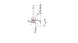
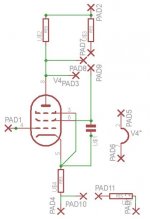
Here is my first attempt at an Eagle schematic and board. It is a 6SJ7 driver board with a jumper for pentode and triode. (now that I think of it I should add a pad for feedback). I used some the tube libraries that others (thanks George) kindly provided in the past. I was thinking about DIYing a bubble etch tank. Does anybody know where to find those blue tripod shaped trimmer pots in the Eagle libraries? How do they look?
Edit: Ok I just looked at those again and have to route those traces arould the tube pads better!!
Edit: Ok I just looked at those again and have to route those traces arould the tube pads better!!
Attachments
Last edited:
Banned
Joined 2002
Ok, more work
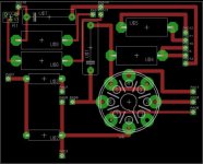
Its just a 6SJ7 pentode driver stage. I figured if I was going to go through the trouble of homebrewing a board I might as well add some flexability. This is nowhere near as cool as the D3a boards that dsavitsk had made but still fun")
Here it is with feedback option, the ground pad becomes the feedback input... And the eagle files.
Not bad, what is it ? Can i help u ? Send me the egl files and i help
Jase
Its just a 6SJ7 pentode driver stage. I figured if I was going to go through the trouble of homebrewing a board I might as well add some flexability. This is nowhere near as cool as the D3a boards that dsavitsk had made but still fun
Here it is with feedback option, the ground pad becomes the feedback input... And the eagle files.
Attachments
The Eagle tube libraries' octal sockets are not sized correctly. You can download properly sized parts from pete millett's site, or from tubelab's site.
thanks for the heads up. I got the ocal socked from a library named "Tubes" I downloaded from here but who knows where it came from so I'll check what got vs the known correct version.
Ok one last post
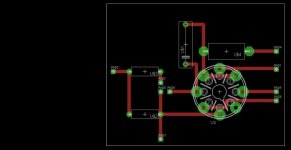
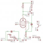
Ok so I added the feedback to the board. you can have a trimmer + resistor or just a resistor, all of which is bypassed by a cap. Now I'm sure I could optimise the footprint of the parts used, ie cap/resistor size and what not, I'll need some help/segestions. What do you guys think?
Athos
Ok so I added the feedback to the board. you can have a trimmer + resistor or just a resistor, all of which is bypassed by a cap. Now I'm sure I could optimise the footprint of the parts used, ie cap/resistor size and what not, I'll need some help/segestions. What do you guys think?
Athos
Attachments
One more
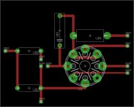
I altered the layout. I have one more in the wings where I added extra pads for plate to plate feed back and a feedback arrangement in a schematic I might try first. I've been playing with this program all week and have a 6SN7 phase splitter and the Dynaco self spliting low power PP amp crammed onto the 3X4 space Eagle allows you (is that the Freeware limit? or can you make that box in the board window bigger??)
So on to etching. I'm planning on going the Amonium Persulphate route with a bubble tank and a heater. For the board I was thinking of going the Laserjet + Iron transfer method. More Pictures of boards as I get bored (sorry).
I altered the layout. I have one more in the wings where I added extra pads for plate to plate feed back and a feedback arrangement in a schematic I might try first. I've been playing with this program all week and have a 6SN7 phase splitter and the Dynaco self spliting low power PP amp crammed onto the 3X4 space Eagle allows you (is that the Freeware limit? or can you make that box in the board window bigger??)
So on to etching. I'm planning on going the Amonium Persulphate route with a bubble tank and a heater. For the board I was thinking of going the Laserjet + Iron transfer method. More Pictures of boards as I get bored (sorry
).Attachments
A few comments:
- You should add at least a grid stopper. And other resistors, particularly Rk, should probably be closer to the pins.
- Heater traces look a little thin -- you might try just putting the pad by the pins and running the wires directly there -- no need to use traces at all.
- the pads used for mounting holes are likely too small for screws
For a similar project to yours, take a look at ecp.cc
Thanks!
All of those are easy fixes, thanks for the input. I agree about the heater traces, I want to keep all the tracks as thick as possible.
Has anybody used double sided boards with some sort of rivets for the through holes? I'm thinking about the soft (hopfully copper) rivets that you put through the holes and then hit with a special tool to curl the ends?
A few comments:
- You should add at least a grid stopper. And other resistors, particularly Rk, should probably be closer to the pins.
- Heater traces look a little thin -- you might try just putting the pad by the pins and running the wires directly there -- no need to use traces at all.
- the pads used for mounting holes are likely too small for screws
For a similar project to yours, take a look at ecp.cc
All of those are easy fixes, thanks for the input. I agree about the heater traces, I want to keep all the tracks as thick as possible.
Has anybody used double sided boards with some sort of rivets for the through holes? I'm thinking about the soft (hopfully copper) rivets that you put through the holes and then hit with a special tool to curl the ends?
Yeah but...
That would be so less fun! If I could I'd wind my own transformers, stuff my own caps and cast my own resistors I would.
Have you looked at Olimex? You can get 2 Eagle sized boards for under $40. When you add up copper clad boards, chemicals, rivets, drill bits, and time, it makes etching your own a bit of a waste.
That would be so less fun!
If I could I'd wind my own transformers, stuff my own caps and cast my own resistors I would.thanks for the heads up. I got the ocal socked from a library named "Tubes" I downloaded from here but who knows where it came from so I'll check what got vs the known correct version.
Its best to buy a tube socket and measure the pins etc to make sure it is right before you make the PCB as there are so many different ones out there.
I have never used Olimex, but I would highly recommend BatchPCB by the SparkFun people. Double sided boards cost $2.50 per square inch plus a modest setup fee. The downside is it takes a while to get the boards back.
Agreed this isn't as immediate and fun as etching your own, but after a few batches of crappy-looking homebrew PCBs, I was positively giddy at the professional-looking, thru-hole plated, board I designed for some nixie tubes.
They also give you a silk-screen layer, so you can go crazy with your PCB art.
So on to etching. I'm planning on going the Amonium Persulphate route with a bubble tank and a heater. For the board I was thinking of going the Laserjet + Iron transfer method. More Pictures of boards as I get bored (sorry
I prefer Muriatic acid and peroxide as an etchant. Easy to get ahold of easy to neutralize and dispose of (but you never need to, it only gets better with use).
Personally, I'd make thicker traces everywhere. The more copper left on the board, the less the etchant has to work.
As to the PCB layout: connect the wiper to the other end of the pot as well - that way if the wiper loses contact momentarily it doesn't go open circuit. Heater lines should be thicker. I like to put the board mounting holes as close to the tube socket as possible to minimize flex and stress when inserting and removing the socket. Are you really tied to that 3 pin cluster arrangement? If not, re-arranging could give you space to run the lines differently. I'd also try to give more clearance around solder pads - some like U$4 and U$7 look very close assuming the pads are the same size on both layers.
Copper rivets are an interesting idea. Very nice combo of turret board durability and PCB ease, but I'd be worried about how much time it would take to heat up that much mass. I'd also worry about damaging the PCB when hammering them flat (I've used the mild steel ones before) and getting solder under them to make a good connection.
Last edited:
Thanks for all the suggestions
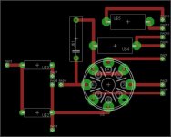
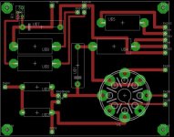
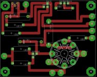
Here is the board now. Thicker traces, bigger pads, relocated heater pads, fixed the trimmer pot and added a stopper. I like the jumper clusters because all the jump points are next to each other. I'll probably block out big areas prior to etching to go easy on my solution. I'll research the Muriatic acid and peroxide, I like the look of the other solution because of the non-staining aspect. Thanks again everybody for the comments. More as my supplies arrive, or I change something.
Here is the board now. Thicker traces, bigger pads, relocated heater pads, fixed the trimmer pot and added a stopper. I like the jumper clusters because all the jump points are next to each other. I'll probably block out big areas prior to etching to go easy on my solution. I'll research the Muriatic acid and peroxide, I like the look of the other solution because of the non-staining aspect. Thanks again everybody for the comments. More as my supplies arrive, or I change something.
Attachments
- Status
- This old topic is closed. If you want to reopen this topic, contact a moderator using the "Report Post" button.
- Home
- Amplifiers
- Tubes / Valves
- First try at an Eagle Schematic/board