The hibrid amp...
Yes...me too!!")
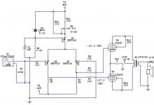
but the capacitor C1 must be connected in parallel with zener and not as in your schematic...as if it is connected as in the schematic you will ended with hum at the output!
cheers
Think it will work?
Yes...me too!!
but the capacitor C1 must be connected in parallel with zener and not as in your schematic...as if it is connected as in the schematic you will ended with hum at the output!
I hope so!!Think it would sound ok?
cheers
Yes, you think it will work, or yes, you had the same idea?
I don't understand why the capacitor where its at would be a problem. It is bypassing the current source mosfet's gate to ground. Maybe I should add another cap across the zener?
Thanks for the reply... there dosen't seem to be a lot of interest.
Steve
I don't understand why the capacitor where its at would be a problem. It is bypassing the current source mosfet's gate to ground. Maybe I should add another cap across the zener?
Thanks for the reply... there dosen't seem to be a lot of interest.
Steve
what's is bypassing what...
Yes but the source of the Q3 mosfet is referenced to the + 40volts rail...so the bypassing capacitor must be connected to the same rail for the mosfet doesn't "see" the hum voltage...and don't amplifie it
regards
I don't understand why the capacitor where its at would be a problem. It is bypassing the current source mosfet's gate to ground.
Yes but the source of the Q3 mosfet is referenced to the + 40volts rail...so the bypassing capacitor must be connected to the same rail for the mosfet doesn't "see" the hum voltage...and don't amplifie it
regards
As shown, you are DC coupled to the 6L6, which is nice. But you have no way of knowing whether your anode currents are out of balance and causing transformer core distortion, or of correcting imbalance. If you use separate 1R cathode resistors, you can detect imbalance, and you could add a servo feedback loop for correction, or add a manual tweak.
What advantage do you expect to gain from your proposed circuit over traditional glass driver circuitry?
Usually, hybrids go the other way, with glass to drive MOSFETs in a desperate effort to get rid of the output transformer.
What advantage do you expect to gain from your proposed circuit over traditional glass driver circuitry?
Usually, hybrids go the other way, with glass to drive MOSFETs in a desperate effort to get rid of the output transformer.
As shown, you are DC coupled to the 6L6, which is nice. But you have no way of knowing whether your anode currents are out of balance and causing transformer core distortion, or of correcting imbalance. If you use separate 1R cathode resistors, you can detect imbalance, and you could add a servo feedback loop for correction, or add a manual tweak.
good idea... I was planning on adding a balance pot on the differential current source to give a little bit of an adjustment for balance. I think when I simulated it before, I used a 100 ohm with the wiper attached to the current source and the legs attached to each mosfet. This seemed to correct for DC imbalances, but AC is another problem. Any ideas?
What advantage do you expect to gain from your proposed circuit over traditional glass driver circuitry?
Well, I guess the appeal is 1 gain stage in the front end with a fairly low output impedance. If I could find a way to balance it, I could drive multiple pairs of tubes with a lower impedance output transformer for more power without an additional driver circuit. 2 gain stages total- short signal path. Also, no caps in the signal path (not that it really matters, but it's kind of cool
)Yeah, I've looked into doing that, but the circuit gets really complex when you have to drive the mosfet gate capacitance (white cathode follower or something similar)... I don't really see the point. If you have the right speakers, transformer coupling isn't necessarily that bad of a thing.Usually, hybrids go the other way, with glass to drive MOSFETs in a desperate effort to get rid of the output transformer.
Yes, the 100R source resistor will do the DC trick.
Do you know how much gm you are expecting, and thus how much gain? AC balance might not be a problem...
I wonder what the input capacitance of your gain stage looks like?
Most people object slightly to output transformer defects, and a lot to how much they have to pay for them. That seems to be the main incentive for MOSFET output stages. As you say, the large, and changing input capacitance is a pain.
Do you know how much gm you are expecting, and thus how much gain? AC balance might not be a problem...
Honestly, no. In my simulation of it I am able to drive the circuit above with 1V p-p and get full output. The output stage is basically taken straight from the RCA databook.
I could always match the differential mosfets and used matched output tubes... maybe then it would be alright?
The input that needs current...
Yes the input capacitance will be great...the gate source capacitance of the mosfet +the Miller capacitance ( the gate drain capacitance X the gain of the stage)...it will need some driving current in the high frequencys...
Mosfets are not my choice for input devices...
cheers
I wonder what the input capacitance of your gain stage looks like?
Yes the input capacitance will be great...the gate source capacitance of the mosfet +the Miller capacitance ( the gate drain capacitance X the gain of the stage)...it will need some driving current in the high frequencys...
Mosfets are not my choice for input devices...
cheers
At maximum output, one output valve has its grid at 0V (a -17.5V swing) and the other at 35V (a +17.5V swing). Thus, there is 35Vpk-pk between the outputs of your driver stage. If there is 1Vpk-pk going in, then you have a gain of 35, and since Av = gmRL, that suggests gm = 35mA/V for the MOSFETs. It probably would be worth matching the MOSFETs, as they are notorious for device variation.
The gain issue...
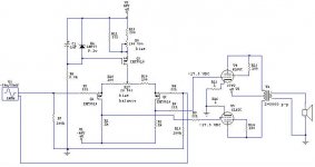
The gain can't be 35 because the degeneration source resistors...1k/100=10...and with the pot in series with the source resistors the gain will be even less...
Thus, there is 35Vpk-pk between the outputs of your driver stage. If there is 1Vpk-pk going in, then you have a gain of 35, and since Av = gmRL, that suggests gm = 35mA/V for the MOSFETs.
The gain can't be 35 because the degeneration source resistors...1k/100=10...and with the pot in series with the source resistors the gain will be even less...
Re: The input that needs current...
I don't see the problem, unless you are using a tube preamp with a fairly high output impedance. The P-channel differential pair is used in all the Pass Aleph amps with no problems, so...???
I understand that a lot of you tube guys like to use all tubes, so it could be an issue.
I will most likely be using it with a zen balanced line stage, which will drive it with no problems.
So, then (I ask myself) why use tubes? It's different. I haven't seen anybody doing it this way. Maybe there's a reason for that, haha. I'm going to give it a go anyway.
Thanks for all the help
Steve
Tube_Dude said:
Yes the input capacitance will be great...the gate source capacitance of the mosfet +the Miller capacitance ( the gate drain capacitance X the gain of the stage)...it will need some driving current in the high frequencys...
Mosfets are not my choice for input devices...
cheers
I don't see the problem, unless you are using a tube preamp with a fairly high output impedance. The P-channel differential pair is used in all the Pass Aleph amps with no problems, so...???
I understand that a lot of you tube guys like to use all tubes, so it could be an issue.
I will most likely be using it with a zen balanced line stage, which will drive it with no problems.
So, then (I ask myself) why use tubes? It's different. I haven't seen anybody doing it this way. Maybe there's a reason for that, haha. I'm going to give it a go anyway.
Thanks for all the help
Steve
Re: The gain issue...
yeah, you're exactly right! I forgot to look at that when I added the balancing circuit.
Tube_Dude said:
The gain can't be 35 because the degeneration source resistors...1k/100=10...and with the pot in series with the source resistors the gain will be even less...
yeah, you're exactly right! I forgot to look at that when I added the balancing circuit.
Re: The gain issue...
Good point. The simulation that gave the 1V sensitivity must have been run before the 100R source resistors were included. Still, the degeneration will reduce the Miller capacitance, which is handy.
Tube_Dude said:The gain can't be 35 because the degeneration source resistors...1k/100=10...and with the pot in series with the source resistors the gain will be even less...
Good point. The simulation that gave the 1V sensitivity must have been run before the 100R source resistors were included. Still, the degeneration will reduce the Miller capacitance, which is handy.
how about this...
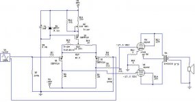
it gives a bias voltage difference of +/- 3.68, and the sensitivity is reduced in half to 2Vp-p for 37V grid-grid (Vpeak) out.
a good compromise?
I'm not sure how much of a voltage difference the output stage would need to see to compensate for imbalance.
it gives a bias voltage difference of +/- 3.68, and the sensitivity is reduced in half to 2Vp-p for 37V grid-grid (Vpeak) out.
a good compromise?
I'm not sure how much of a voltage difference the output stage would need to see to compensate for imbalance.
Attachments
- Status
- This old topic is closed. If you want to reopen this topic, contact a moderator using the "Report Post" button.
- Home
- Amplifiers
- Tubes / Valves
- simple hybrid idea