I never realized how close these two designs were until recently. I know the tubes are a bit different - the AN uses a 6072A and the FP is a 12AU7, but the topology looks very close.
I had a FPIII that I liked but had too much gain so I reluctantly sold it. Since then I had a few pres make the rounds (AN M7 with 5687, a AR SP6C, currently a Audible Illusions L1) but always wanted to rebuild the Foreplay
The other day I decided to rebuild my12B4A pre that was noisy as all get out, so I built the AN M7 around the 5963 (6.3VDC version of the 12AU7) - AN M7 is attached. This thing really impresses me. It does everything as good if not better than the Audible Illusions L1, and just might replace it.
Wondering if I should change the 6K2//5K1 resistor with an LED on first triode. The only difference between the FP and the 12AU7 AN M7 is the FP has 22K on anode of first tube and 22k on the cathode of second tube, while the AN has 120K on both...also the FP has the LED while the AN has the two resistors (6K2//5K1)
Anyway, any thoughts?
Attachments
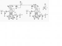
I cobbled together the circuit and as I said, sounded very nice. Noticing the differences in the M7 and FP (and 6SN7 VTV too), and also noticing that I really wasn't pulling much current compared to the 12B4 (The 12B4 pulled quite a bit, but that's per design). So not being able to leave well enough alone, I made some modifications.
I doubled up the 120K resistors and took a quick survey of voltages. I kept the resistance the same on front plate and back cathode (is this important?) Seeing that the overall amp was pulling only 11 ma total (both channels). I then "forced" the front end into more current by replacing the 4K5 resistors (3.2V across) with a red LED (2V across), doubling the current from 1.4ma to 2.8ma.
Anyway, the circuit before and after the LED is below. Comments? I know the 5963 max plate voltage is 250V and I am at 262V...big deal?
Attachments
Last edited:
I have finally had a chance to listen to this pre as it now stands (lower circuit on above schematic) and it sounds very good. It now has all the sonic attributes the Audible Illusions Modulus L1 I have.
I would still like comments on the circuit ( my current 5963 operating points, etc)
The Power supply is a Triad N68X wired in reverse to get 220V secondary through a FWBR (4 x 1N4007) followed bay a CRCR filter (270uf/450V, 25R, 270uf/450V, 1K) giving a B+ of around 275V with a 12ma loading.
I would still like comments on the circuit ( my current 5963 operating points, etc)
The Power supply is a Triad N68X wired in reverse to get 220V secondary through a FWBR (4 x 1N4007) followed bay a CRCR filter (270uf/450V, 25R, 270uf/450V, 1K) giving a B+ of around 275V with a 12ma loading.
KMTANG --> Funny you should mention the 7N7,
At work we found an old box of vacuum tubes from when the control room was all tubes years ago. Didn't expect to find many usable tubes, I saw a couple 6L6, 6V6, 6Y6 and got a little excited...brought a box home full of tubes (in original RCA/GE/Sylvania boxes) and found a bunch of 5963 tubes (researched to find out that they are 6.3V heater versions of 12AU7), along with some nice clean RCA 2A3 (whoa), a couple boxes (4 per box) of new 7N7, 5691 (RCA red base - see one pair on ebay going for $90 now), 5692, 5693's too...a few 7F7, 80, 57...all in all about 50 tubes, and still more boxes to go through at work - a genuine treasure find...also found Very Good Condition Knight 600C tester - but my friend got that...
I was just ready to start my 7N7 preamp (got my loctal sockets yesterday) around the 6SN7 VTV design (I need another preamp and amp like I need a hole in my head)
Keep me posted on your 7N7 preamp - got a schematic?
Last edited:
John,
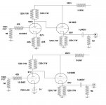
I don't remember where I read it but I tried it on my same topology 6SN7 pre and it works,just tie the cathode followers load res directly to the cathode of the first stage.
You can only do this if your anode res of the first stage is the same value with the cathode res of the second.Try and comment.
Mike
Schematic
Hi John65B,
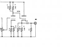
I don't have the schematic. However, I believe it is very easy:-
The 10M45 - I set it to 5 and 6.5mA for the 1st and 2nd stage. The Radj = 3.0Vref/current. The required for 5mA should be 3/5 = 0.6Kohm. A 1k resistor is connected in serial with the Gate for oscillation supression. You may find the detail in TUBELAB.COM.
The 1st stage is with 2 red LED bias. The cathod voltage is at 3.58V. The Plate voltage is about half B+ for the 1st stage.
The circuit is very simple and with good result.
JOhnny
Hi John65B,
I don't have the schematic. However, I believe it is very easy:-
The 10M45 - I set it to 5 and 6.5mA for the 1st and 2nd stage. The Radj = 3.0Vref/current. The required for 5mA should be 3/5 = 0.6Kohm. A 1k resistor is connected in serial with the Gate for oscillation supression. You may find the detail in TUBELAB.COM.
The 1st stage is with 2 red LED bias. The cathod voltage is at 3.58V. The Plate voltage is about half B+ for the 1st stage.
The circuit is very simple and with good result.
JOhnny
- Status
- This old topic is closed. If you want to reopen this topic, contact a moderator using the "Report Post" button.
- Home
- Amplifiers
- Tubes / Valves
- Audionote M7 and Foreplay III