Hey Rich. Thanks for the feedback.
I'll propably set up the feedback loop one of these days when I have a free minute. -> That can wait. fundamental operation first.
The chokes magnetic axis is oriented exactly away from the signal wires and into 2mm sheets of grounded iron.
-> Becareful..laying too much iron also radiates more, unless a screened box is used. A single higher inductance choke would improve.
I hate to mention it, but rotating the mains toroid can also change the hum field. Toroids are far from perfect transformers, unless magnetically screened with a iron band.
What do you mean by "shortcut the first stage"? Seperate the first 6SN7s coupling caps from the second one and shorten the second ones grids to ground?..
-> Leave all interstage coupling caps as they are in circuit. Simply short circuit amp signal input and listen for any hum difference.If hum increases then input stage grounding needs improving. That's all.
(If a large bass reflex speaker is used, then this will show up hum far more).
The DC line shift (this is bad) is probably caused by those wretched wind turbine power modules with a non symmetric zero shift.
I currently have the heater referenced about 25V up, but I can try grounding them via a pot, I have a 100W wirewound one in my box somewhere. But shouldn't hum from the heaters have disappeared when I set up a DC heater supply?
Yes, generally. Since you have a DC heater then you won't improve much more. You mention lifted off 25V off ground, presume with a decoupled hivalue cap ?
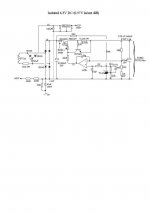
Have a look at the pic enclosed. I assume yours is sim.This is one of my older discrete circuits of the early 1970's with excellent performance and I regulary use this. Ferrite beads are required to dampen the mosfet. On Lower LH side, the 47uF cap on the split off ground lift off plays a big part in eliminating the commonmode hum component.
The world is short of single brick high current LowDrop out regulators over 2A.
The nub: As one picks up experience and the learning curve, the last powerful weapon is global nfb. This will reduce hum and linearise amplifier performance and one will wonder why one didn't implement it from the beginning to solve all problems ! Fundamental experience with what youv'e got is important for another project.
Adding global nfb can add alot of it's own problems; this must be treated separately.
richy
Attachments
First of all I made two pictures of the amp guts. Perhaps I made a simple mistake and you guys see it instantly.
PSU
Those metal sheets are connected directly to ground, cause I wanted to keep the magnetic field out of the amp as good as possible.
Amplifier part
Now that might look a little ugly, but I'm just not one of those people who can manage to get a circuit to look beautiful, but to me most of it makes sense. The signal carrying wires are all kept close to the bottom (which is the top of the case, since we're looking from the under side) and at an angle to the heater and high voltage wires. The heaters are led 'up high' and then come straight down over the socket.
The signal is running at the upper side twisted together with it's signal input ground, at the top right corner they part as the signal goes into the circuit. The first solder joint on it is the star of the first stage, combining the reservoir caps and the cathode resistors. The second solder joint is the ground wire from the second stage star which can be seen lower. The ground bar then goes back to the top side and is led to the output star, which is the ugly thing hovering between the bias pots. It is then led to the output jack, where it meets the ground wire coming from the PSU star, the wire which, via antiparallel diodes, connects to mains earth and of course COM from the OPT.
So there is the possibility that it is inducing it's own noise into the circuit now.
But I somehow don't believe it, because the noise hasn't changed between AC and DC supply.
Secondly, 'high value': 2,2uF decouples the heater bias, as indicated by the schematic. That not realy high value, but what I found in all similar circuits.
Thirdly, from what I've heard up until now, I propably am not the guy for gNFB. You never know if it's gonna be different with this amp, and I'm gonna try it out, but with other amps I've heard I felt it took away the drive and life of the music a bit.
PSU
Those metal sheets are connected directly to ground, cause I wanted to keep the magnetic field out of the amp as good as possible.
Amplifier part
Now that might look a little ugly, but I'm just not one of those people who can manage to get a circuit to look beautiful, but to me most of it makes sense. The signal carrying wires are all kept close to the bottom (which is the top of the case, since we're looking from the under side) and at an angle to the heater and high voltage wires. The heaters are led 'up high' and then come straight down over the socket.
The signal is running at the upper side twisted together with it's signal input ground, at the top right corner they part as the signal goes into the circuit. The first solder joint on it is the star of the first stage, combining the reservoir caps and the cathode resistors. The second solder joint is the ground wire from the second stage star which can be seen lower. The ground bar then goes back to the top side and is led to the output star, which is the ugly thing hovering between the bias pots. It is then led to the output jack, where it meets the ground wire coming from the PSU star, the wire which, via antiparallel diodes, connects to mains earth and of course COM from the OPT.
Firstly: Yeaaaaaaaaah, no. My 'DC supply' is a highly complex part consisting of ... a rect bridge and all my high value caps in parallel. *coughs*Yes, generally. Since you have a DC heater then you won't improve much more. You mention lifted off 25V off ground, presume with a decoupled hivalue cap? Have a look at the pic enclosed. I assume yours is sim.
So there is the possibility that it is inducing it's own noise into the circuit now.
But I somehow don't believe it, because the noise hasn't changed between AC and DC supply.
Secondly, 'high value': 2,2uF decouples the heater bias, as indicated by the schematic. That not realy high value, but what I found in all similar circuits.
Thirdly, from what I've heard up until now, I propably am not the guy for gNFB. You never know if it's gonna be different with this amp, and I'm gonna try it out, but with other amps I've heard I felt it took away the drive and life of the music a bit.
The signal is running at the upper side twisted together with it's signal input ground, at the top right corner they part as the signal goes into the circuit.
Top left, not top right...
Herr,
Drop your input impedance by lowering R3 from 1M to 100k or even 50k. This will also lower your gain slightly, but most importantly it should reduce the noise as the input will act less like an antenna. The previous comment about the gain in that circuit is very true. You have a high impedance input with a high gain amplifier. Great broadband tuner.
The original tube selection for these amps was based on having feedback. If you want to reduce the required feedback you may have to select a lower mu tube down the road or use a more aggressive voltage divider on the input. I did the same thing with the mullard kt88 I am building. I didn't want 30dB feedback so I used lower mu inputs and ltp. I don't know how this applies to a Williamson, but I assume it can be.
Venturing abit with global nfb; these types of amps with single stage front end gain with concertina + Williamson driver with UL o/p stage, start to show instability when total global nfb is around 35dB. In most cases these amps sound best with about 15dB global nfb. Based on figures on previous posts, that implies a gain reduction of about
5.6x, so the input sensitivity will drop from roughly 75mV x 5.6 = 0.42V rms for full o/p. With that the hum and noise will drop proportionally. These figures are rough approximations.
Around 500mV is a good starting level for most CD players and line amps with a basic volume control.
My guess is that with your amp in the present working condition without global nfb, you will hear noticeable hiss from a treble unit.
richy
I tried lowering R3 to 65k. (without any feedback still)
Sadly that didn't change anything. Even when i shortcut the signal input, it doesn't do that much. (The noise gets a little less loud, but not realy much)
I also tried damping the driver tubes mechanicaly which didn't do anything neither. The 5692 seems to be quite invulnarable to microphony, since even additionaly applied manipulation directly to the tube didn't reflect in the speakers at all.
I switched back to AC heating too, since the DC heater didn't improve things.
Richy, a gain reduction by X would be achieved by lowering R3 by the same factor?
Richy, a gain reduction by X would be achieved by lowering R3 by the same factor?
No, not the same. You may think it's the same effect by reducing the input resistors but there is a totally different relationship.Global nfb effects the whole amplifier. In a nutshell;
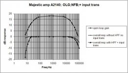
Your circuit has an open loop characteristic set by circuit gains of all tubes. A closed loop (global nfb in our case) is a small calculated sample signal taken from the output and sent back to the input (usually cathode) and will reduce the gain, I've mentioned a typ figure of 15dB for this type of amp (in the example 15dB =5.6x gain reduction) which will flatten and extend the overall amplifier response. There are restrictions to how far one can do this without running into instability at both upper and lower frequency ends and requires skill. The first step is to plot an open loop response.
See enclosed pic. This tube amplifier is a top notch 150W performer and the top curve in graph of open loop gain of amp without global nfb, and your amp would have something sim, perhaps response falling off bit sooner at the upper end. No two curves are the same, the o/p tranny being the unpredictable component. The remainder of the graph is with global nfb connected and optimised. Notice how smooth and stretched the response has become.This isn't snake oil. The only sacrifice is loss of gain.
My favourite to do the many performance graphs after an amp has been designed, as the purpose is to ensure stability and proper performance with long loudspeaker leads and various loudspeakers. It is a long physics subject but very fascinating one.
I let Morgan Jones book Valve amps 3rd edition page 407 complete the rest of the stability thesis as this is eventually the design finale of global nfb..
The hiss problem. Make sure the anode resistor of the first 6SN7 is a good quality one.
Keep at it !
richy
Attachments
Ok, regarding the NFB: I changed the phases of the tubes at the OPT and connected the NFB loop. Something really strange happens, which happend too when I tried changing the phase on the level of the input stage: Blue glow appears on the glass of the OP tubes, then the air around the plates starts to glow blue intensivly and cracks can be heard through the speaker. At that point I always shut the amp off, because that can't be good now, can it? It doesnt matter though if NFB is connected for this phenomenon to appear. If I change the wires at the OPT back, it disappears. But it's wrong phased that way, since NFB results in motor boating.
Last edited:
Don't connect the global nfb yet. The amp isn't ready. We have to determine it has no problems and can function with power, and the sound qualityis reasonable. The blue glow is probably RF oscillations. We will need to determine the value of the global nfb resistor and other components required. It pays to study the diagrams of other amplifiers and you will see the general arrangements and some alterations of the 1st stage anode components.
richy
richy
Okay. But since this penomenon accurs even when NFB is not connected, I wonder how simply changing the phases at the OPT can cause such a thing. After all I thought I knew it shouldn't matter which tube is connected to which input of the OPTs primary.
If someone was to come to this thread, here is a list again what I tried already to get rid of the noise in the amp:
1. Lower the input impedance / shorten the input
2. DC heating
3. Reference the heaters to ground instead to 25V+
4. Damping the input tubes mechanicaly
5. Exchange all the tubes
Things on my to-try-list:
- Do the heater referencing via a pot
But I feel that this isnt going to be the solution. The pot might get rid of the very little 100Hz noise that I have, but the noise bugging me is of a higher freqency.
Not realy, but there isn't a giant amount of wire between them and the socket either. I know that they are supposed to be as close as possible and with the output tubes I acutaly soldered them directly to the socket. But the one for the input stage has aprox 2" of wire. I can correct that though if rendered necessary.
STOP!
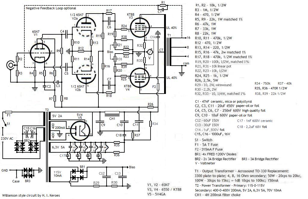
DOUBLE CHECK the o/p stage tubes are correctly connected; screen grid to screen grid tap and anodes tap on each respective side of each half primary. Check you haven't got anodes and screens swapped. If it is wrong, this is the quickest way to ruin a set of good o/p tubes by destroying the screen grids.
TIP:-
When powering up for the first time even if correctly wired, temporarily use 470R 0.25W resistors in each screen grid (g2).....this will limit the screen current and will go o/c if something is wrong.
I checked everything three times, all the values are right and everything is connected correctly, there are no short wires. The one thing I could possibly think of is that I didn't connect Pin 1 to anything. It's connected to the metal base of the tube. Should that be grounded? That really can't be it.
I don't understand why this blue glow thing should happen. The two sides of the OPT should be absolutly equal. Although of course I only use the 4 Ohm tap and leave the other ones unconnected, but that is really the last thing I could think of and it shouldn't matter either.
I don't understand why this blue glow thing should happen. The two sides of the OPT should be absolutly equal. Although of course I only use the 4 Ohm tap and leave the other ones unconnected, but that is really the last thing I could think of and it shouldn't matter either.
Last edited:
Pin 1 to anything. It's connected to the metal base of the tube. Should that be grounded? That really can't be it.
I don't understand why this blue glow thing should happen. The two sides of the OPT should be absolutly equal. Although of course I only use the 4 Ohm tap and leave the other ones unconnected, but that is really the last thing I could think of and it shouldn't matter either.
Pin I is normally grounded. However, I've seen many designs which is just ignored. You need to ascertain that the output stage is drawing the correct current, as I suspect the blue glow could be high quiescent current. You need to measure the volts across the cathode resistors with no signal. For basic measurements I always start with quite a low value 40-50mA just to start off with. It can be increased later.
I've never known this kind of amp with 6SN7's to start oscillating; there should be no sign of oscillations, without global nfb.
Make sure you are working with a dummy load. The quiescent current should be quite steady.
richy
Herr, can you post critical voltages? Bias, Plates, Cathode, etc?
EDIT - whoops, just saw you posted some of the voltages on previous post...
"I have set the quiescent current to 65mA running the amp in pure Class A"
What power are you at in Class A at that bias and B+?
EDIT - whoops, just saw you posted some of the voltages on previous post...
"I have set the quiescent current to 65mA running the amp in pure Class A"
What power are you at in Class A at that bias and B+?
Last edited:
Looking at the Genelax Datasheet, drawing a load line from 500V 0mA to 0V 250mA (Raa of the OPT is ~4k, so every tube should see 2k, right?) and looking at 65mA takes us to a bias voltage of -47V and a power out of around 24W per tube. But as always: I can be wrong.
- Status
- This old topic is closed. If you want to reopen this topic, contact a moderator using the "Report Post" button.
- Home
- Amplifiers
- Tubes / Valves
- With a little help... KT88 PP UL Amp