Many many years ago at college we were taught that a transformers primary winding was wound on first to give the tightest magnetic coupling, then the secondary windings were put on. I was quite happy with this explanation as every transformer I came across seemed to agree with this practice. However the other day I came across a simple push-pull output transformer which had its 3 Ohm secondary wound on first, with the centre tapped primary winding wound on top.
This has me puzzled but I bet there is a good reason for it. Then I began to think about the primary over winds, surely one half of the centre tapped winding has more effect on producing the magnetic field as it is closer to the core than the other winding? OK, maybe this is crap and by the laws of physics both windings have the same effect?
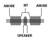
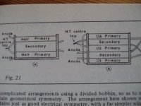
Going on from this, would it not make sense to have a symmetrical transformer as shown? Or maybe I am just getting too old for this game now")
This has me puzzled but I bet there is a good reason for it. Then I began to think about the primary over winds, surely one half of the centre tapped winding has more effect on producing the magnetic field as it is closer to the core than the other winding? OK, maybe this is crap and by the laws of physics both windings have the same effect?
Going on from this, would it not make sense to have a symmetrical transformer as shown? Or maybe I am just getting too old for this game now
Attachments
Unfortunately it is not really that simple at all, primaries and secondaries are composed of multiple interleaved windings wired in series (sometimes also in parallel) in order to reduce leakage inductance (which is an inverse function of how well the windings couple to each other. Reduced leakage inductance implying better coupling) - typical good output transformers may have 7 or more interleaved primary and secondary windings. There is a trade off between interleaving to reduce leakage inductance and capacitive coupling (parasitic capacitance) between the windings. Resonances manifested as peaks and dips in the frequency response of the transformer hint at equivalent parallel and series resonant parasitic circuits in the primary windings (the fewer and more benign these resonances the better the quality of construction of the transformer) which in a decent transformer will be well above the audio band and well controlled.
Others will explain this far better than I have, but this hints at some of the issues.
It is not nearly as simple as the explanation you were given.
Others will explain this far better than I have, but this hints at some of the issues.
It is not nearly as simple as the explanation you were given.
Last edited:
As kevinKr mentions; the real world of push pull design is a compromise in physics because frequency plays a massive part.
Most audio tranny manufacturers that is those who are left typically make 7-14 section interleaved prim/sec designs. Some will custom to 18sect Williamson or Partridge at greater cost. Top designs use separate secondaries for series parallel matching.
Whats the performance difference between 7,14,18 sect designs ? Quite alot. Alot depends on the circuit topology used, and the degree of feedback used. If the feedback can include the transformer then the amplifier reponse can be flattened and extended. For some a contentious issue.
All custom makes use symmetrical winding construction for best balance, so the winding resistances are equal. I find the Sowter 7-14 sectioned designs sonically clean with 20dB global nfb give good open low end response, the UL anode to screen winding taps respond relatively easy to zobel snubbing, ringing occurs around 70Khz upwards.With high gm tubes this is often required. The fourier response equation requires a transformer bandwidth so that the 3rd harmonic doesn't droop more than -3dB at 3x the highest audio frequency. The rule of thumb is 20Khz x3 = -3dB at 60Khz. This is the minimum achievement for HiFi. We need high bandwidth to express wavefront rise-time as some instruments can have steep uS waveforms, in a view of expressing definition.
The 18 sectioned from others and NOS have even more complex winds and expensive. On merits, the upper leakage capacitances are slightly higher,requiring more careful snubbing so these designs are better for parallelled push pull stages. My own view is that the 18 sectioned designs are harder to optimise but give a more precise sound and can handle upper audio frequencies better. This can make the 1st stage phase compensation and feedback loop components tricky to optimise.
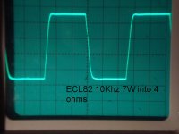
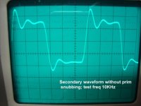
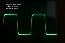
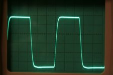
Enclosed are some waveforms. The Unsnubbed is typical of all p-p transformer undamped waveforms, the 10Khz squarewave test is very revealing of how all works. The procedure of damping primary resonances is the same from the uncomplicated 7 sect 7W ECL82 to the complicated 100W parallelled p-p types. Notice the cleanness of the 14 sect Sowter 8659.The 18 sect Majestic with sharper flank was alot harder to optimise, some auditionists mentioned it offers ultimate classical reproduction sound. So there we have it.
There isn't anything easy about this subject: One thing is quite sure, je bigger the transformer for wider b/w, expense rockets. The rule of thumb, an o/p tranny for 40Hz is half the size of a 20Hz beast. E string is around 41Hz so for M-instrumentation amps there's no need to go lower.
Je bigger for HiFi, LF performance is great, but HF response curtails as size goes up. Big isn't always beautiful.
Good luck
richy
Most audio tranny manufacturers that is those who are left typically make 7-14 section interleaved prim/sec designs. Some will custom to 18sect Williamson or Partridge at greater cost. Top designs use separate secondaries for series parallel matching.
Whats the performance difference between 7,14,18 sect designs ? Quite alot. Alot depends on the circuit topology used, and the degree of feedback used. If the feedback can include the transformer then the amplifier reponse can be flattened and extended. For some a contentious issue.
All custom makes use symmetrical winding construction for best balance, so the winding resistances are equal. I find the Sowter 7-14 sectioned designs sonically clean with 20dB global nfb give good open low end response, the UL anode to screen winding taps respond relatively easy to zobel snubbing, ringing occurs around 70Khz upwards.With high gm tubes this is often required. The fourier response equation requires a transformer bandwidth so that the 3rd harmonic doesn't droop more than -3dB at 3x the highest audio frequency. The rule of thumb is 20Khz x3 = -3dB at 60Khz. This is the minimum achievement for HiFi. We need high bandwidth to express wavefront rise-time as some instruments can have steep uS waveforms, in a view of expressing definition.
The 18 sectioned from others and NOS have even more complex winds and expensive. On merits, the upper leakage capacitances are slightly higher,requiring more careful snubbing so these designs are better for parallelled push pull stages. My own view is that the 18 sectioned designs are harder to optimise but give a more precise sound and can handle upper audio frequencies better. This can make the 1st stage phase compensation and feedback loop components tricky to optimise.
Enclosed are some waveforms. The Unsnubbed is typical of all p-p transformer undamped waveforms, the 10Khz squarewave test is very revealing of how all works. The procedure of damping primary resonances is the same from the uncomplicated 7 sect 7W ECL82 to the complicated 100W parallelled p-p types. Notice the cleanness of the 14 sect Sowter 8659.The 18 sect Majestic with sharper flank was alot harder to optimise, some auditionists mentioned it offers ultimate classical reproduction sound. So there we have it.
There isn't anything easy about this subject: One thing is quite sure, je bigger the transformer for wider b/w, expense rockets. The rule of thumb, an o/p tranny for 40Hz is half the size of a 20Hz beast. E string is around 41Hz so for M-instrumentation amps there's no need to go lower.
Je bigger for HiFi, LF performance is great, but HF response curtails as size goes up. Big isn't always beautiful.
Good luck
richy
Attachments
Here's a vintage Dynaco PP OPT I dissected... for your study.
diytube.com :: View topic - The A470 OPT, an interesting work of art.
For PP guitar amps, I personally wind them either S-P-S-P-S or S-P-S, depending if the cleint wants a hotter, brighter output or cooler, subdued Jazzy/Bluesy output.
Cheers!
diytube.com :: View topic - The A470 OPT, an interesting work of art.
For PP guitar amps, I personally wind them either S-P-S-P-S or S-P-S, depending if the cleint wants a hotter, brighter output or cooler, subdued Jazzy/Bluesy output.
Cheers!
Here's a vintage Dynaco PP OPT I dissected... for your study.
For PP guitar amps, I personally wind them either S-P-S-P-S or S-P-S, depending if the cleint wants a hotter, brighter output or cooler, subdued Jazzy/Bluesy output.
Cheers!
For the absolute simplicity see pic. Results can be suprising. (b) is a better quality version than (a). Obviously suss the phase out.
Geek, that Dynaco (a nightmare as it is) is near sequence to the Philips 20W pattern.
richy
Attachments
Hi Richy,
That (a) is pretty much like every vintage economy transformer I've rewound, while (b) was when they wound for balanced DCR is somewhat higher quality (6V6) units.
Speaking of these images, there was a page on the web that described a good 1/2 dozen windups and I lost my bookmark to it. Do you know the site?
I don't believe I've had the honour of gutting a Philips transformer. Thanks for the info
Cheers!
For the absolute simplicity see pic. Results can be suprising. (b) is a better quality version than (a). Obviously suss the phase out.
That (a) is pretty much like every vintage economy transformer I've rewound, while (b) was when they wound for balanced DCR is somewhat higher quality (6V6) units.
Speaking of these images, there was a page on the web that described a good 1/2 dozen windups and I lost my bookmark to it. Do you know the site?
Geek, that Dynaco (a nightmare as it is) is near sequence to the Philips 20W pattern.
I don't believe I've had the honour of gutting a Philips transformer. Thanks for the info
Cheers!
Geek could it be this one ?
Welcome to the most complete do it yourself guide on the D. T. N. Williamson tube amplifier.
r:-
Welcome to the most complete do it yourself guide on the D. T. N. Williamson tube amplifier.
r:-
I get emails on "what to do's", regarding procedures with large p-p o/p trannies, i.e above 100W at low frequencies. The challenges and complexes are there, those o/p trannies weighing 15- 20Lbs#10Kg or so is no trivial business. Designing power amps in this upper power segment requires careful thought with test equipment and layout, the scope earthing leads and so on.
Following the discussion from posts 2,3; those square wave pics were obtained from a 4 stage amp with feedback loop and phase correction designed using the K transfer function calculation, with o/p transformers having 20Hz cutoff. The result that optimised circuits can accept a total of 36dB global nfb i.e onset instability. However, when an o/p tranny down to 15Hz is on the bench i.e +35% bigger, and to get a clear HF response at 150W the circuit design isn't quite so clear cut. As the size rockets, the leakage and capacitive parasitics double up, far more copper area, and greater through-winding capacitance begins to suck power je higher the frequency.
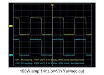
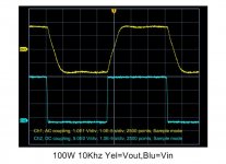
Actual parallel push-pull amplifier test with a 150W tranny specified at 15Hz throughput (this is a massive lump):- notice the square waveforms at 1Khz and 10Khz. Both taken at the 100W level. The 1Khz is near original whereas the 10Khz has rise and fall drastically slewed and the waveform resembles a "sandcastle". This amp used for demo is stability optimised: one cannot get a better squarewave quality as the limitations of bandwidth in the output transformer become the restricting frequency element. The distortion at 150W at 1Khz is typ 0.2%; so at 10Khz to be around 1% or more.The open loop curve of an amp designed with such a transformer looks like an upped' half moon.. Generally,all p-p transformers exhibit rising thd with rising frequency. Again, depends on circuit topology and amounts of global nfb used.
This is why paralled o/p tubes are often used in parallel-p-p to lower the impedance hence reducing turns= lower losses. To get 10Khz at 150W power without overshoots and strays requires skill. Things will get hot, any snubbers must be sensibly rated.
So when designing tube amps, keep to amicable power throughputs, lower and smaller output transformers are much easier to use. Consider the bandwidth implications of what is absolutely necessary, HiFi and/or MI.
richy
Following the discussion from posts 2,3; those square wave pics were obtained from a 4 stage amp with feedback loop and phase correction designed using the K transfer function calculation, with o/p transformers having 20Hz cutoff. The result that optimised circuits can accept a total of 36dB global nfb i.e onset instability. However, when an o/p tranny down to 15Hz is on the bench i.e +35% bigger, and to get a clear HF response at 150W the circuit design isn't quite so clear cut. As the size rockets, the leakage and capacitive parasitics double up, far more copper area, and greater through-winding capacitance begins to suck power je higher the frequency.
Actual parallel push-pull amplifier test with a 150W tranny specified at 15Hz throughput (this is a massive lump):- notice the square waveforms at 1Khz and 10Khz. Both taken at the 100W level. The 1Khz is near original whereas the 10Khz has rise and fall drastically slewed and the waveform resembles a "sandcastle". This amp used for demo is stability optimised: one cannot get a better squarewave quality as the limitations of bandwidth in the output transformer become the restricting frequency element. The distortion at 150W at 1Khz is typ 0.2%; so at 10Khz to be around 1% or more.The open loop curve of an amp designed with such a transformer looks like an upped' half moon.. Generally,all p-p transformers exhibit rising thd with rising frequency. Again, depends on circuit topology and amounts of global nfb used.
This is why paralled o/p tubes are often used in parallel-p-p to lower the impedance hence reducing turns= lower losses. To get 10Khz at 150W power without overshoots and strays requires skill. Things will get hot, any snubbers must be sensibly rated.
So when designing tube amps, keep to amicable power throughputs, lower and smaller output transformers are much easier to use. Consider the bandwidth implications of what is absolutely necessary, HiFi and/or MI.
richy
Attachments
Geek could it be this one ?
Welcome to the most complete do it yourself guide on the D. T. N. Williamson tube amplifier.
r:-
Nice transformer page, but the egregious errors in the electronics analysis elsewhere on that site don't instill a lot of confidence in me that the information is correct. Is it?
Geek, that Dynaco (a nightmare as it is) is near sequence to the Philips 20W pattern.
richy
hey-Hey!!!,
That 'nightmare' is not all that difficult to wind. The detail tat caught my eye was the difference in turns count between the two parallel sections. I've not gotten/discovered a consistent answer as to determining the best 'mismatch'. The Peerless outputs I've taken apart had none of that sort of thing, but in the case of the big 20-20 Plus series S-271-S I had unwound the secondary was far more complex, and the TX also had electrostatic shields too.
As soon as I can get a good drawing of that one's wind geometry I'll put it up here. After seeing a few of them sell on ebay I regretted not selling mine only a little bit...
cheers,
Douglas
- Status
- This old topic is closed. If you want to reopen this topic, contact a moderator using the "Report Post" button.
- Home
- Amplifiers
- Tubes / Valves
- PP Output Transformer design