Folks,
After lurking and contributing for a while, I'm finally starting my first thread. To mark the occasion, I figured some introduction is in order.
I design semiconductors for a living. Currently I'm designing precision timing products (ultra-low noise clock generators). Prior to that I designed precision op-amps (5 uV offset, 145 dB AVOL, 20 nV/degC TC(Vos) kind of stuff). So I know my way around most sand based analog circuits. But I've never worked with vacuum tubes. I've decided to give it a whirl.
My end goal is to design a medium powered (20-30 W, P-P) tube amp. But I figured I'd start small, so I've decided to build a Spud based on a 6LU8 Compactron. I'll use the triode section as a preamp/driver for the pentode section. Much like the Tubelab Simple SE (thanks George for making that available!). I don't expect to get neighborhood-leveling power out of it - a watt or two would be nice. But I would like reasonably low distortion and audio bandwidth out of it.
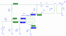
I got some el-cheapo OPT's from Antique Electronic Supply. Just something cheap to blow up before spending real money... I measured the equivalent circuit parameters of the OPT using an HP 4194A Impedance Analyzer:
Lseries = 60 mH
Lprimary = 2.59 H
Rseries = 772 Ohm
Cparallel = 43 pF
To develop a SPICE model for the 6LU8 tube, I used Norman Koren's MATLAB script. It does a fair job, I'd say. But then I'm not looking to predict exact circuit performance here, just get an idea of if it'll work or not.
I have performed circuit simulation and built the circuit in the lab. The simulation seems to jive quite well with lab experiments with the exception of the screen current that seems to be a bit higher in simulation.
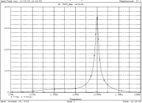
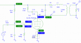
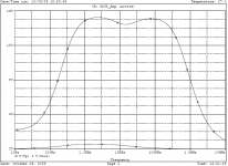
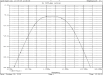
Circuit schematic #1 shows my first setup and the first AC response plot shows the plate voltage. There's a huge peak in the frequency response caused by the resonance of Cparallel and Lseries of the OPT. I have replicated this in the lab. Apparently, I'm not the only one with that issue as this guy places 10 nF across the primary. I tried that, but it really kills the bandwidth. With 10 nF across the primary, I'm getting -3 dB frequencies of roughly 300 Hz and 4 kHz. Now, the 200 Hz I was expecting. After all, the OPT is tiny! But 4 kHz?! So I tried a snubber across he primary (schematic #2). Much better. The resulting plate voltage (2nd plot) and output voltage (3rd plot) look decent. The sim says I should expect the -3 dB BW to be 300 Hz ~ 13.5 kHz. So not exactly HiFi, but half decent.
Here's my list of questions:
- I realize my OPT probably isn't the greatest in the World, but is there any way I can squeeze more usable bandwidth out of this?
- I have not seen many tube circuits that employ snubbers across the OPT primary. Am I just being innovative or is there a better way to combat the resonance of Lseries and Cseries?
- What are typical values for Lseries and Cseries of better/bigger OPT's? It strikes me as an odd design choice to have those resonate so close to the audio band. Or is it just me?
Thanks in advance.
~Tom
After lurking and contributing for a while, I'm finally starting my first thread. To mark the occasion, I figured some introduction is in order.
I design semiconductors for a living. Currently I'm designing precision timing products (ultra-low noise clock generators). Prior to that I designed precision op-amps (5 uV offset, 145 dB AVOL, 20 nV/degC TC(Vos) kind of stuff). So I know my way around most sand based analog circuits. But I've never worked with vacuum tubes. I've decided to give it a whirl.
My end goal is to design a medium powered (20-30 W, P-P) tube amp. But I figured I'd start small, so I've decided to build a Spud based on a 6LU8 Compactron. I'll use the triode section as a preamp/driver for the pentode section. Much like the Tubelab Simple SE (thanks George for making that available!). I don't expect to get neighborhood-leveling power out of it - a watt or two would be nice. But I would like reasonably low distortion and audio bandwidth out of it.
I got some el-cheapo OPT's from Antique Electronic Supply. Just something cheap to blow up before spending real money... I measured the equivalent circuit parameters of the OPT using an HP 4194A Impedance Analyzer:
Lseries = 60 mH
Lprimary = 2.59 H
Rseries = 772 Ohm
Cparallel = 43 pF
To develop a SPICE model for the 6LU8 tube, I used Norman Koren's MATLAB script. It does a fair job, I'd say. But then I'm not looking to predict exact circuit performance here, just get an idea of if it'll work or not.
I have performed circuit simulation and built the circuit in the lab. The simulation seems to jive quite well with lab experiments with the exception of the screen current that seems to be a bit higher in simulation.
Circuit schematic #1 shows my first setup and the first AC response plot shows the plate voltage. There's a huge peak in the frequency response caused by the resonance of Cparallel and Lseries of the OPT. I have replicated this in the lab. Apparently, I'm not the only one with that issue as this guy places 10 nF across the primary. I tried that, but it really kills the bandwidth. With 10 nF across the primary, I'm getting -3 dB frequencies of roughly 300 Hz and 4 kHz. Now, the 200 Hz I was expecting. After all, the OPT is tiny! But 4 kHz?! So I tried a snubber across he primary (schematic #2). Much better. The resulting plate voltage (2nd plot) and output voltage (3rd plot) look decent. The sim says I should expect the -3 dB BW to be 300 Hz ~ 13.5 kHz. So not exactly HiFi, but half decent.
Here's my list of questions:
- I realize my OPT probably isn't the greatest in the World, but is there any way I can squeeze more usable bandwidth out of this?
- I have not seen many tube circuits that employ snubbers across the OPT primary. Am I just being innovative or is there a better way to combat the resonance of Lseries and Cseries?
- What are typical values for Lseries and Cseries of better/bigger OPT's? It strikes me as an odd design choice to have those resonate so close to the audio band. Or is it just me?
Thanks in advance.
~Tom
Attachments
Congratulations, you've just discovered that pentodes without feedback are not terrifically good for driving cheap transformers. You have several possible paths:
1. Use overall feedback from the secondary of the transformer to the input.
2. Use local feedback from the plate of the pentode to the grid to drop its source impedance to something reasonable.
3. Use a triode.
4. Use a better transformer.
The RC network has been used on occasion by designers in the past, but it's a band-aid for lousy iron, and as you see, it is not without penalty. I don't know Lpri and Lleakage specs for good SE transformers, but I bet someone who does will pipe up.
Glad you've come out of the closet and decided to post! Always nice to have knowledgeable engineering types around.
I pretty much agree with SY, but further his suggestion #2.
Suggestion #1, using loop NFB around the whole transformer and electronics can cause other problems, stability mostly, if youuse enough NFB to handle the OPTs deficiencies.
#3 & 4 defeat you initial task of doing it really cheaply.
But #2 can make a serious improvement to a cheap OPT, at no disadvantage except a loss of some gain. One simply adds a R from the power tube's anode to the anode of the driver, or if you don't use a driver then you have to add an extra R to make the output tube into a "summing junction" type of opamp concept.
The FB R has to be chosen as a compromise between results and lowering gain.
I've gone as far as having a 1:1 ratio in these two Rs, but 10:1 would be a fair starting place.
Using this concept, I got a cheap toridal power transformer to work VERY well as an OPT in a P-P amp.
Regards, Allen (Vacuum State)
PS Love to talk to you about low (phase) noise xtal oscillators.
Ideally, the OT should be designed so that the resonance is critically damped by the load Zl ie: (1/(wCp)=wLs = Zl). The xfmr at hand appears to have way too much Lseries, so probably has minimal or no interleaving. Getting the pentode Zout down by local neg. feedback (plate to grid resistor-cap.) is the classical fix.
But #2 can make a serious improvement to a cheap OPT, at no disadvantage except a loss of some gain. One simply adds a R from the power tube's anode to the anode of the driver, or if you don't use a driver then you have to add an extra R to make the output tube into a "summing junction" type of opamp concept.
This is the technique popularized by the RH84, of which you will find lots of info on this forum.
I have 2 RH84, an excellent amp for almost no money. The parafeed monobloks with EF86 (triode) drivers based on iron from a couple Grundig consoles have embarrased some pretty expensive SE amps.
dave
PS Love to talk to you about low (phase) noise xtal oscillators.
Yes please... i'd love to see a superCLock from Allen that mere mortals like myself could afford
")
dave
The 6LU8 / 6LR8 spud has been developed before. In fact two of them were developed nearly simultaneously with very similar schematics. One was mine, the other was developed on another forum. You can do all of the thinking, or just copy ours, or just use it for ideas.
http://www.diyaudio.com/forums/showthread.php?t=125963&highlight=spud
http://www.diyaudio.com/forums/showthread.php?t=125963&highlight=spud
Congratulations, you've just discovered that pentodes without feedback are not terrifically good for driving cheap transformers. You have several possible paths:
1. Use overall feedback from the secondary of the transformer to the input.
2. Use local feedback from the plate of the pentode to the grid to drop its source impedance to something reasonable.
3. Use a triode.
4. Use a better transformer.
The RC network has been used on occasion by designers in the past, but it's a band-aid for lousy iron, and as you see, it is not without penalty. I don't know Lpri and Lleakage specs for good SE transformers, but I bet someone who does will pipe up.
Glad you've come out of the closet and decided to post! Always nice to have knowledgeable engineering types around.
Tom,
I suggest you combine items 1 and 2 on SY's list. The bulk of the NFB is plate to grid, but a few dB. of GNFB will linearize the cheap O/P "iron". Be sure to roll infrasonic noise and most of the 1st octave off at the I/P. A GNFB error correction signal trying to extend LF response too far will (YUCK) saturate the O/P trafo's core.
With the superior test equipment at your disposal, getting phase compensation right should not be especially difficult.
I suggest you combine items 1 and 2 on SY's list.
I am not a big fan of GNFB in SE amp designs, but a little could help with these OPT's.
I would go for #2 (plate to plate feedback in both designs), #3 triode (or UL) wire the output section, and maybe #4. If the amp works good enough, then spring for the Edcor XSE15-8-5K OPT's. This amp rocks with them, $30 each.
I'll throw in the use of grounding the cathode through the secondary. This will lower the output impedance and increase bandwidth considerably. Just watch the phase so you don't use positive feedback instead.
This will result in a little DC across the speaker, due to the DC resistance of the secondary. It's not likely to be a problem, but this can be avoided by connecting an electrolytic capacitor from cathode to speaker side of the secondary.
Arh... Output impedance
That was actually the thread that inspired me to start with a spud. While a lot of value can be gained from reverse engineering someone else's circuit, I find that I don't really understand something fully until I'm able to do it myself. So I figured I'd start for myself and see when I got stuck... But it is nice with a shoulder to look over every now and then.
Applying some negative feedback around the pentode (1 Mohm from plate to input and a 10 kOhm between the input and the signal generator) extended the usable bandwidth quite a bit and allowed me to tweak the snubber to be less aggressive. With a 5.6k+1.2nF snubber I'm seeing 120 Hz ~ 19 kHz bandwidth without signs of instability or oscillation. Extending the lower end will require more iron (I already have two of the Edcor XSE15-8-5K on order) and 19 kHz is above what I can hear anyway. So good enough for now.
I'm not getting any appreciable power out of it, though. I think I'll try to get the bias point off the ground. Crankin' up the amperage! I might also try triode-strapping the thing. I'll keep you posted.
Thank you for all the replies. I greatly appreciate it.
~Tom
The 6LU8 / 6LR8 spud has been developed before. In fact two of them were developed nearly simultaneously with very similar schematics. One was mine, the other was developed on another forum. You can do all of the thinking, or just copy ours, or just use it for ideas.
http://www.diyaudio.com/forums/showthread.php?t=125963&highlight=spud
That was actually the thread that inspired me to start with a spud. While a lot of value can be gained from reverse engineering someone else's circuit, I find that I don't really understand something fully until I'm able to do it myself. So I figured I'd start for myself and see when I got stuck... But it is nice with a shoulder to look over every now and then.
Applying some negative feedback around the pentode (1 Mohm from plate to input and a 10 kOhm between the input and the signal generator) extended the usable bandwidth quite a bit and allowed me to tweak the snubber to be less aggressive. With a 5.6k+1.2nF snubber I'm seeing 120 Hz ~ 19 kHz bandwidth without signs of instability or oscillation. Extending the lower end will require more iron (I already have two of the Edcor XSE15-8-5K on order) and 19 kHz is above what I can hear anyway. So good enough for now.
I'm not getting any appreciable power out of it, though. I think I'll try to get the bias point off the ground. Crankin' up the amperage! I might also try triode-strapping the thing. I'll keep you posted.
Thank you for all the replies. I greatly appreciate it.
~Tom
The guys above have basically covered it.
To summarize for the newbies following this thread:
You get a low frequency 6dB /octave roll off due to the output tube internal impedance (rp) and the primary inductance Lprimary.
You get 2 high frequency 6dB/octave roll offs (a combined 12dB/octave roll off)
1 due to rp and the leakage inductance Lseries
1 due to rp and the distributed interwinding capacitance which is represented by that Cparallel term. Cparallel is the equivalent parallel capacitance.
All three roll offs are affected by output tube rp. Lower rp will shift the low frequency roll off lower and the 2 high frequency roll offs higher.
rp may be reduced by:
1)Global NFB from the output transformer secondary (can have stabilization problems)
2) Local NFB via shunt feedback from the output tube anode (plate) back to the grid, note the plate of the output tube to the plate of the driver tube is effectively the same thing.
3)Ultralinear connection
4)Triode strapping
5) Use the transformer secondary in the cathode of the output tube to give cathode feedback.
All of the above work - I used the plate to plate feedback plus Ultralinear methods in my push pull Baby Huey Amps which are posted here. The RH84 uses plate to plate feedback in a single ended design.
Using the output transformer secondary for cathode feedback also works well to reduce output tube rp but my experience with it suggests that it works best with higher quality output transformers where the need for such a method is less anyway.
Cheers,
Ian
P.S Also look at Pete's design here:
http://www.diyaudio.com/forums/tubes-valves/151206-posted-new-p-p-power-amp-design.html
Last edited:
I'll throw in the use of grounding the cathode through the secondary. This will lower the output impedance and increase bandwidth considerably. Just watch the phase so you don't use positive feedback instead.
Apologies to resurrect an old thread. Just check the SE design by Claus Byrith on the Lundahl website and use the secondary for feedback.
An old trick to get badly matched opt's to sound good was to have nfb from the speaker out put socket of the amp.
Say for a mullard 5-10 or 5-20 copy amp they (repair techs) would come off the negative side of the out put socket with a 6k ohm 2 watt with a mullard mustard 330pf in parallel,
Then they would have a 180 ohm 1w with the other end connected to nothing
(it's meant to have some kind of capacity).
From that point they would put a second 6k ohm 2w in series with the first and then on to the nfb wire connecting to the first stage of the amp.
Also they would up the screen resistors by as much as double their original value.
it was known as the multi impedance set and all the resistors would be carbon film type.
- Status
- This old topic is closed. If you want to reopen this topic, contact a moderator using the "Report Post" button.
- Home
- Amplifiers
- Tubes / Valves
- How to avoid oscillation and get max BW out of crappy OPT