I finally got a 'scope up and running, and I just put 'er to the El Cheapo that I built last spring. Mine has a a different power supply, 390R cathode resistors on the 6V6's, a 120pf cap from the postive speaker lead to ground (per EliD's suggestion) and a lower LP filter on the front end (all per EliD's suggestion). I also added toggles for UL and NFB.
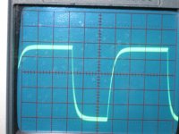
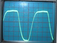
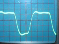
A 10K square wave looks darn good to me with the feedback switched off (old Sherwood iron). However, when I flip the feedback on, it causes some ringing. (I attached pics of the wave from my signal generator, and from with amp without and then with feedback, into an 8 ohm non-inductive load). So, my understanding is that I need to adjust the value of the cap, right? What would be some good values to order?
I also checked to see how much power I could get before visible clipping. In triode mode, I'm getting around 7 watts, then clipping as you approach 8. Just as you'd expect. However, I get about half that in UL before the sine starts to flatten. What on earth does that mean?
Finally, I seem to be having a problem measuring high frequency extension with the signal generator and load. I'm seeing the voltage decrease dramatically as you approach and cross even 10K. I assume this is a problem with my measurement setup?
thanks for your help,
Paul
www.wildburroaudio.com
Attachments
PJ,
Phase compensation in EC is brute force. The inductive WW 'T7 loads peak HF gain. The cap. between speaker "hot" and ground shorts the NFB loop out above a certain freq. Try 100 pF. and 150 pF. to see which gives better ringing behavior. The object of the exercise is to keep error correction signals small.
Phase compensation in EC is brute force. The inductive WW 'T7 loads peak HF gain. The cap. between speaker "hot" and ground shorts the NFB loop out above a certain freq. Try 100 pF. and 150 pF. to see which gives better ringing behavior. The object of the exercise is to keep error correction signals small.
Will do. I presume I can experiment with ceramic caps, and then buy something nicer when I find a value that works. Any thoughts on the low power in UL?
Paul
www.wildburroaudio.com
Paul
www.wildburroaudio.com
Hi Paul,
I'd like to question the use of a 10KHz square wave for testing an amplifier with an output transformer. Especially one that's large enough to pass frequencies down to 30Hz. It is unreasonable to ask such a transformer to pass a 10KHz square wave. With it's very large number of odd order harmonics, it would require a bandpass of 100KHz to reproduce a 10KHz fundamental without distortion. A 2KHz fundamental is the excepted general standard for testing out to 20KHz.
The waveform shown coming out of your generator shows a serious loss of high frequency response and risetime (rounding off). This could be do to the generator itself, or to the poor response of the oscilloscope used to display it. It may also be your setup to the amplifier. Square wave signal sources like to be terminated in their characteristic output impedance. This is done at the amplifier end of the connecting cable and is generally 600 ohms, or 50 ohms for the better (faster risetime) units. Proper coaxial cable is also required.
Square wave testing should be done at a level well below the overload point of the amplifier. Due to the nature of square waves, an amplifier can be easily overloaded and the square wave response made to appear better then it actually is. Although the output of yours isn't all that bad, and it's a lot better then some I've seen.
Thanks for your advice. The generator is an arthritic old HP. The thing I find interesting is that I hear it's frequency waver substantially when connected to a speaker, yet I don't see a variance on the 'scope. Either I'm misunderstanding something, or I figured out why I sometimes struggle with intonation!
It isn't a fancy scope, though I was using seemingly proper wires and a suitably low output level. I choose the 10K wave not only because I had seen it suggested for such a purpose (as a newbie, I simply follow the advice of others), but also because it was easier to photograph and compress. The wiggle I'm asking about also appears in a 1K square wave (as you'd expect), but I feared it would be more difficult to see in this admittedly low-res reproduction.
So, no matter what, I appreciate the education. I'll try some different caps ASAP. But I'm still wondering what to look for re: my apparent problem with UL.
Paul
- Status
- This old topic is closed. If you want to reopen this topic, contact a moderator using the "Report Post" button.