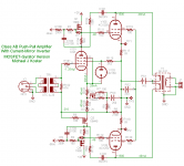
Got this idea when I was thinking of how to make a Schade SE into ABPP. The iron used in my simulation is the Lundahl LL1667 540H/5mA as I have a pair lying around. Servo is Rods.
Sims so nice but I doubt I will try it. If I build anyway, E280F(close to D3a) from my present stock will be used as driver.
Sims so nice but I doubt I will try it. If I build anyway, E280F(close to D3a) from my present stock will be used as driver.
An externally hosted image should be here but it was not working when we last tested it.
Got this idea when I was thinking of how to make a Schade SE into ABPP. The iron used in my simulation is the Lundahl LL1667 540H/5mA as I have a pair lying around. Servo is Rods.
Sims so nice but I doubt I will try it. If I build anyway, E280F(close to D3a) from my present stock will be used as driver.
That somehow looks quite familiar...
But cathode bias for class AB? What happens on musical dynamics as the total cathode current changes?
I keep thinking that with this topology you could get away with any class A to AB transition point and the Schade feedback would linearize the transition (except class B of course). Probably still best to match the curves for relatively constant aggregate Gm.
That's a clever servo design; but I think that some adjustment scheme should be stable enough to stay within 5mA imbalance. Hmm trouble free though, and unlikely to have sonic impact.
Is the coupling through the inductor doing anything useful? I'm think of using gyrators or mu-gyrators and forget about balancing the front end. The MOSFET could even be run at higher Id for larger gfs.
http://www.diyaudio.com/forums/showthread.php?p=1927419
Are you concerned about signal balance side to side; the finite MOSFET gfs will reduce the mirrored signal level somewhat relative to the input-driven side.
Cheers,
Michael
Last edited:
That somehow looks quite familiar...
Hey Michael,
Sorry I didn´t mention your 5842 spud
") .
.About AB cathode bias I wouldn´t worry. Plays great in my ears and has always done. No problem to change to fixed though. But that wasn´t the main issue here.
I simmed with gyrators first and both coupled and uncoupled inductors. The coupling has to be there, period! Or coupled gyrators, can you fix them please
?About signalbalance, it is perfect with coupled inductors.
Do you want the file to play?
Hey Michael,
Sorry I didn´t mention your 5842 spud
About AB cathode bias I wouldn´t worry. Plays great in my ears and has always done. No problem to change to fixed though. But that wasn´t the main issue here.
I simmed with gyrators first and both coupled and uncoupled inductors. The coupling has to be there, period! Or coupled gyrators, can you fix them please
About signalbalance, it is perfect with coupled inductors.
Do you want the file to play?
Lars, I was referring to the one attached below, where the signal current loops are pretty much the same as yours above (except for the common inductor core) and yes I do have a differential gyrator ;-) but I'm not sure of it's role without running the sim myself.
Thanks, I would like to play with this!
Michael
Attachments
Last edited:
- Status
- This old topic is closed. If you want to reopen this topic, contact a moderator using the "Report Post" button.