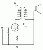
If you have just the one stage, then there's just one choice: Anode Follower.
Pardon my ignorance but ... what is "spud" for ?
An amp with only one tube is a "one-tuber"...
A potato is a "tuber"...
Slang for potato is "spud"...
Therefore a one-tube amp or one-tuber is a spud.
makes sense, right???
If you have just the one stage, then there's just one choice: Anode Follower.
I'm having trouble picturing how this will work -- am I just taking one side of the secondary and connecting it to the grid through a resistor? Or just take right from the plate ... presumably through a cap?
What tube?
12HG7 to start with. With a 5K:32 OPT for headphone use.
You can ground the cathode resistor through the second coil or part of it. Add a cathode capacitor to increase the gain of the stage as well.
Mind the direction of the coil.
I think that I have seen that done, but I can not remember where.
If you have not purchased the transformer yet then you could specify one specifically for cathode winding feedback. Tim de Paravicini did that in his EAR HP4 headphone amp.
If you have not purchased the transformer yet then you could specify one specifically for cathode winding feedback.
Unfortunately, I'm on a DIY diet, so the only option is to reuse what I have. The EAR seems to have its own little winding for this.
Last edited:
This way is allmost impossible practically. The set of R-s are wery hard to select due to numerous contradictory requirements. If you stick on this way, take the signal from the plate (trough a C) for far easier matching (high-Ohm Rfb2).So, something like this?
Yep.
OK, then the $100 question -- any hints on how to calculate these feedback resistors.
This way is allmost impossible practically. The set of R-s are wery hard to select due to numerous contradictory requirements. If you stick on this way, take the signal from the plate (trough a C) for far easier matching (high-Ohm Rfb2).
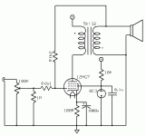
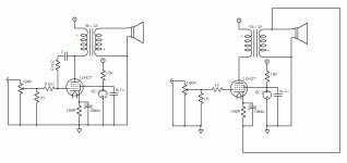
I attached a possible schematic below to see if this is what you mean. Any C and R suggestions there?
You can ground the cathode resistor through the second coil or part of it. Add a cathode capacitor to increase the gain of the stage as well.
Mind the direction of the coil.
Also on the schematic. Is this what you have in mind?
Attachments
I think that I have seen that done, but I can not remember where.
If you have not purchased the transformer yet then you could specify one specifically for cathode winding feedback. Tim de Paravicini did that in his EAR HP4 headphone amp.
I made a SE EL84 amp a while back grounding the cathode through the secondary. http://www.diyaudio.com/forums/showthread.php?t=121767&highlight=jerluwoo The problem in doing that way makes it basically a unity gain stage that will require a driver.
That may well have been where I saw it. I also just remembered that Jan E has an amp with transformer cathode feedback on his site: http://www.veiset.net/PX25/index.html . Not now applicable to dsavitsk, but interesting anyway.
Dsavitsk, I think the feedback equations are available in the Designing Single-Stage Inverting Feedback Amplifiers section of http://www.aikenamps.com/
: )
Dsavitsk, I think the feedback equations are available in the Designing Single-Stage Inverting Feedback Amplifiers section of http://www.aikenamps.com/
: )
1.Not easy task! Ex. Rfb2=1M, Rfb1=22k, C=100n. The feedback will depend on the position of the pot.1.I attached a possible schematic below to see if this is what you mean. Any C and R suggestions there?
2.Also on the schematic. Is this what you have in mind?
2.Yes.
Right. It's 100% feedback. You need a coil's tap to lower it.The problem in doing that way makes it basically a unity gain stage that will require a driver.
1.Not easy task! Ex. Rfb2=1M, Rfb1=22k, C=100n. The feedback will depend on the position of the pot.
That's probably not good ...
Right. It's 100% feedback. You need a coil's tap to lower it.
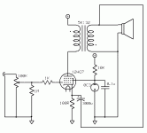
100% feedback is fine as phones rarely need any more than a buffer. The problem, however, is that the secondary winding DCR is ~6 ohms. With 20mA of current through the tube, that puts 120mV of DC on the headphones, which is way too much. What if only the Rk bypass cap goes to the secondary with the resistor going straight to ground?
Attachments
Last edited:
That's probably not good ...
100% feedback is fine as phones rarely need any more than a buffer. The problem, however, is that the secondary winding DCR is ~6 ohms. With 20mA of current through the tube, that puts 120mV of DC on the headphones, which is way too much. What if only the Rk bypass cap goes to the secondary with the resistor going straight to ground?
Why not triodestrapping w/o NFB instead? You´ll still get 1W instead of pentode 2,5W with Ia=40mA.
- Status
- This old topic is closed. If you want to reopen this topic, contact a moderator using the "Report Post" button.
- Home
- Amplifiers
- Tubes / Valves
- Single Ended Pentode Spud and Feedback


