Is there any sonic benefit to be had by using a larger coupling cap than the smallest one required to give your desired LF rolloff between couple stages?
One would assume (there's that word ) that if you double the size of the cap, you effectively halve its ESR across the working frequency range.
Obviously there's a cost/size penalty to be paid, is there a sonic upside or penalty?
In the amp I'm building the calculated interstage coupling cap is 0.47uF and while I have a 0.47uF Wima MKP4, I also have a couple of 2.2u Auricaps sitting around doing nothing. If using the Auri's is going to sound markedly better then I figure why the heck stick with the Wimas?
One would assume (there's that word
) that if you double the size of the cap, you effectively halve its ESR across the working frequency range.Obviously there's a cost/size penalty to be paid, is there a sonic upside or penalty?
In the amp I'm building the calculated interstage coupling cap is 0.47uF and while I have a 0.47uF Wima MKP4, I also have a couple of 2.2u Auricaps sitting around doing nothing. If using the Auri's is going to sound markedly better then I figure why the heck stick with the Wimas?
...is there a sonic upside or penalty?
It could depend on the circuit. In some cases, particularly those involving multiple stages and significant amounts of negative feedback, the values of certain coupling caps may be critical. Changing them could move the dominant pole and result in instability (oscillation). That would definitely qualify as a sonic penalty.
Last edited:
Low frequency roll-off developed by the coupling capacitors might help avoid output transformer saturation under certain conditions. That sounds nasty. There are certainly advocates of bandwidth limiting out there. You can't expect all miracles from iron. On the other hand, if your transformers are capable you should deliver as much of the spectrum as they can handle.
You say you've got the caps in hand. Try it both ways, and see. Let us know how it works out.
You say you've got the caps in hand. Try it both ways, and see. Let us know how it works out.
Input gain stage stage cap coupled to a concertina phase splitter and then cap coupled to triode connected EL84's.
Dat's a lotta caps. Why not AC couple the AF amp to the PS, ala Dynaco ST35?
Ty, really, the only two caps I could potentially delete are the ones between the gain stage and the phase splitter where I could direct couple. The ones coupling the phase splitter to the output tubes are a given. I'm using fixed bias on the output tubes, so there's no cathode bypass caps there and the input and concertina are LED biased so the cathode bypass caps are gone there too.
That being the case I've only got 3 caps sum total in the audio section of the circuit.
It's a test bench amp anyway so I'll build it using the LED bias and the three caps and see how we go, I was just curious to know if there was any audible benefit in using a larger cap size or if anyone had done tests to see.
... I was just curious to know if there was any audible benefit in using a larger cap size or if anyone had done tests to see.
Imperfections in a capacitor: inductance, series resistance, dielectric absorbsion. All these result in losses, changing with frequency. Although the phenomena are measurable capacitor losses are rarely published.
That's why cap A can do a good job in amp topology 1, while not necessary true for cap B or topology 2. From experienced hifi hobbyists it's understood coupling caps better have the smallest value one can come away with.
Imperfections in a capacitor: inductance, series resistance, dielectric absorbsion. All these result in losses, changing with frequency. Although the phenomena are measurable capacitor losses are rarely published.
From experienced hifi hobbyists it's understood coupling caps better have the smallest value one can come away with.
While the coil length will be double in a cap with twice the capacitance, the number of turns will be somewhat less than double due to the increasing diamater of the winding, so twice the capacitance won't be twice the inductance. And with twice the surface area across which to conduct, I'd expect the ESR of the larger cap to be significantly lower (nearly half that) of the smaller value cap.
As far as hobbyists using smaller caps, I'd always figured it was down to lower cost, rather then better sonics.
Is there any sonic benefit to be had by using a larger coupling cap than the smallest one required to give your desired LF rolloff between couple stages?
When using gNFB, there sure is. You can have a billiard table flat frequency response from 20Hz to 20KHz. However, if you're relying on gNFB to do that, then there is a definite sonic penalty. If the open loop response rolls off too soon, then the NFB decreases, forcing the closed loop gain higher to flatten the over all response. Less gNFB means less effective gNFB, and you might have a higher Zo at the lower frequencies, and therefore poorer damping of the woofer(s). This could lead to sloppy bass, as the woofer(s) will tend to produce their self-resonant note rather than the actual notes the musicians played. That tends to sound like monotonic thumping, and is definitely a sonic penalty.
When using gNFB, you also don't want to see the cutoff frequencies of your RC coupled stages clustering around the same frequency, as this will make the phase shift greater than it otherwise would be, and that's an open invitation to instability, or at the very least, a rising amplitude at that frequency that will compromise the sonics.
OTOH, you may not want too low a frequency response. Since vinyl platters are not completely flat, or guitar players don't neatly pluck the strings, you can get low frequency noise that you'd rather not be sending to your speeks.
Last edited:
Think of the context.
ESR in coupling caps is absolutely meaningless. What's the magnitude compared to the load? A part per million or less?
DA is likewise meaningless. This isn't a timing circuit, and the DC conditions are fixed.
DF may arguably be significant- that's an AC parameter.
For feedback amps, one must be quite careful about LF rolloffs. To achieve stability, they need to be staggered, and randomly changing one or two may make the situation much worse.
For any amp, increasing the LF bandwidth increases the need for decoupling on the supply rails. Ignore that and you've got an oscillator. Moreover, if means are not implemented to prevent blocking, larger caps will make that problem worse.
And finally, a completely unsupported subjective opinion: more capacitance means pushing around more dielectric. The changes ought to be in the opposite direction- smaller caps.
Why would it? It depends on imperfections coming from materials used and winding techniques.Yes, but does a bigger cap in the same position sound better than a smaller one?
If I can offer an analogy, I run sound for some bands sometimes. Many mixers have "low cut" or "anti-rumble" buttons either on each channel or a global one. Unless the instrument is a bass or a bass drum, I engage the button. This reduces the risk of bad things happening (e.g. low frequency oscillation feedback) while not affecting the frequency range that the instrument can produce.
At low audio frequencies in 3 or 4 stage p-p tube amps there is an optimum interstage cap value versus amp closed loop response, the wretched output transformer properties being the job killer, being the most critical component determining the lowest frequency range. In summation,
too high interstage cap values will reduce LF thd but at the cost of beat note transient overhang, (muddly sound and poor power handling) this can be too long on recovery as to modulate any other signal with it. This condition with wide b/w output tranfsformers can imply too much LF gain leading to phaseshift instability. With a tube amp on the bench with dummy load and global nfb connected; an applied simulation transient 1-2Hz square wave with a very long mark-space ratio (very short on //long off) is a good test of closed loop performance at very low signal levels (100mW) and a long persistent /storage scope will show this.
Throwing the spanner in the works, there is an optimum closed loop Q alignment, same with the LS driver relationship with the cabinet. 0.7 is slack ultra clean classic , 1-1.4 ideal mixed music, 1.4++ boom box.
As Miles mentions, the problem is one wants enough closed loop circuit damping at the low end to control the LS driver; The method I adopt is to design the amp circuit with an optimum Q of 1; (math brain nightmare) Interestingly in all finished cases I arrive at approx 1% thd at the amplifier o/p output transformer design LF cutoff frequency at rated power.This figure also coincides with the silicon iron characteristics and the whole transformer winding design equations. So in nearly all the designs I examined the loop gain has to be reduced at the lower end by using smaller values of interstage caps.
Looking back previous 40 yrs, Using the 1% thd method in dealing with optimum transient response; in nearly all my closed loop designs of homemade amps with various brands of E&I output trannies there remains +10dB feedback at 20Hz which rises with frequency. This may seem low but we are dealing to tube amps. Enclosed is a closed loop pdf of a top flight 120W parallel p-p amp. This E&I o/p tranny has a LF design cutoff of 15Hz at 150W.
The GEC KT88-50 design is typical, 4n7 or thereabouts. This value seems mighty low (as to suggest a misprint)and must not be increased, otherwise motorboating due to amplifier cap phaseshifts gets close to 180°. None of this is easily described in a few lines of forum work.
I may have detracted slightly from the 6dB cap response problem but amplifier design is highly dependant on cap values and a massive influence on amp and sonic behaviour. In the past it was often an arbitary value obtained by listening, without much understanding behind it.
Read:-Morgan Jones valve amps 3ed p.180 "blocking". also p412 classic power amps.
My advice for first timers in wanting to make a tube amp, stick with a time tested design or risk one skills !
richy
To get things clear, I'm talking about only altering the value of the cap coupling the input and phase splitter stages (although, as has been suggested, I'd be better off going direct coupled there and deleting it completely if possible).
The caps coupling the phase splitter to the outputs will remain as is (although in the future I may roll them for something else nicer than WIMA's if I feel a burning need for upgrades). No matter what I do downstream, the couplers to the output tubes will set a fixed low frequency response limit which I can't go below, even if I couple the earlier stages using 10uf caps instead of 0.47's (not that I intend to).
Much of the discussion thus far has revolved around modifying the bandwidth of the amp and issues to do with feedback. I'm not planning to use loop feedback and I'm not trying to extend the bandwidth of the amp.
The question was intended to be a simple one: Assuming no modification to overall circuit behaviour such as the introduction of motorboating or causing instability in the amp, is there a sonic benefit in using a larger cap to couple in place of a smaller one, or is the converse true?
Disco and Sy seem to be saying that more windings (or more dielectric) equals more problems, this strikes me as an interesting viewpoint given the positive responses most folks seem to have to the Mundorf Supreme caps which have 4 times the windings (double size capacitance series connected with another double size) of a standard cap. Of course this is done with the intent of reducing problems of inductance with the second cap wound in the opposite direction, but it's still more windings and more dielectric.
Curious to know if anyone has actually done a subjective test.
Bigger caps look more impressive. For most, if it looks better and is exotic, it sounds better. But what do I know, I use small Wimas that are cheap and do nothing but perform well.
Problem is, that's not a good assumption.
Assuming no modification to overall circuit behaviour such as the introduction of motorboating or causing instability in the amp
Problem is, that's not a good assumption.
Wima is just fine yes. fkp 1 has also a internal series connection of sorts.
in my amp the dominant cap is 3.5 % of the load it sees, at 15 Hz. i'm fine with that.
it chose a polypropylene-foil audyn there.
on the input at that frequency, the cap there at that frequency is 0.18 % of the load it sees, and hence there is little urge for me to replace it, although it is mkt. i will try some polypropylene-foil one there as well one time though.
when the "hearing" starts, they both will have very little swing over them.
the other dominant things are a choke forming half the load at 10 Hz, and a output transformer half the load after that if not that choke dominated, of 0.7 Hz.
(that audyn would be half the load at 0.5 Hz)
this is how i almost completely shifted the lower reactances out of the audio band and i see no need to go down further.
em but my point is that the influence becomes smaller if it has to work less, that can be a bigger cap, or lighter load, the ideal being a cap working into thin air ;p
there is also the effect of miller capacitances in some topologies, where it may be beneficial that also then the cap remains large compared to thát load.
if it is already designed, it is another story indeed.
Last edited:
... Curious to know if anyone has actually done a subjective test.
I guess we all did audition coupling caps, results wandering over the place. The tightness of the windings ('winding technique') has lately come up as critical note on resonance. The russian FT3 was subject of debate if I recall correctly.
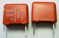
This is my favorite for low level (<25V ac) coupling, wish I had more
More to make a proper comparison that is.
Attachments
Last edited:
wish I had more
Polycarb? And you like them compared to what?
- Status
- This old topic is closed. If you want to reopen this topic, contact a moderator using the "Report Post" button.
- Home
- Design & Build
- Parts
- Audible benefits of larger coupling caps than required?