MOSFETs are great for followers, and supposedly can drive heavy loads, but what are values of output impedance one can expect for the average MOSFET such as an IRF820? The Gms of such devices are huge in the whole amp rages, but the mA ranges are just too small on the scale of the drain curves in the datasheets!
Simply the output impedance is: 1/gm in parallel with Source resistor....
Doesn't make sense to use this device in such an application in the low mA ranges...
The voltage swing will push this into cut-off in typicall audio signals, when biasing it this low, I would have to see the circuit....
At 500mA your gm is about 1.1 S
At 300mA your gm is about .4 S
At 100mA your gm is about .1 S
Very non-linear in this region.... The only way to linearize it somewhat is with a matching resistor in the Drain as you have in the Source....This will maintain constant voltage across the device durring operation and keep the gm more stable....
Any lower than this your gm is in the gutter....
I suggest to pick another FET....
Chris
MOSFETs are great for followers, and supposedly can drive heavy loads, but what are values of output impedance one can expect for the average MOSFET such as an IRF820? The Gms of such devices are huge in the whole amp rages, but the mA ranges are just too small on the scale of the drain curves in the datasheets!
Don't worry about it. For my current project (845 SET) I intend to use the FPQ2N60C N-Channel MOSFET as a source follower grid driver. According to the spec sheet, this one has: Gm= 5000mA/V @ Id= 1000mA. I figure that a static Id= 34.5mA with a 10K tail resistor. Guesstimate the Gm:
Gm(34.5)= 34.5(5000/1000)= 172.5ma/V
Even if this is off, it still beats the living hell out of just about any VT. Figure the Zo:
Zo= 0.1725 || 10E3= 5.8R
Even if "off", that still comes quite close to the ideal Zo= 0, and much closer than any VT.
As for linearity, the 100% NFB inherent to follower design takes care of that.
Cool. I'm sure my IRF820s will be fine, although I will be running them at only around 6mA - I'm making a Pimm style CCS/mu-follower. I may have to rethink the design, because even taking into account what you said, I think 6mA may just be too low for this MOFSET. If I was driving output grids then obviously I'd have no problem with running at higher currents!
Perhaps I could use a signal device as the lower mosfet (in a way similar to Gary Pimm's battery biased CCS)
Cool. I'm sure my IRF820s will be fine, although I will be running them at only around 6mA - I'm making a Pimm style CCS/mu-follower. I may have to rethink the design, because even taking into account what you said, I think 6mA may just be too low for this MOFSET. If I was driving output grids then obviously I'd have no problem with running at higher currents!
Perhaps I could use a signal device as the lower mosfet (in a circuit similar to Gary Pimm's battery biased CCS but that uses IRF820s for both the upper and lower devices of the cascade)
Cool. I'm sure my IRF820s will be fine, although I will be running them at only around 6mA - I'm making a Pimm style CCS/mu-follower. I may have to rethink the design, because even taking into account what you said, I think 6mA may just be too low for this MOFSET. If I was driving output grids then obviously I'd have no problem with running at higher currents!
Perhaps I could use a signal device as the lower mosfet (in a way similar to Gary Pimm's battery biased CCS)
If that's what you're trying to do, then how about a Kimmel Mu Stage design instead? That way, you can run the MOSFET at a higher current, and still give the VT the 6mA it wants.
If driving a pair of EL84 or other easy to drive tubes then you don't need huge current in the MOSFET follower. 3mA is ample for EL84 drive. The problem with MOSFET Source Followers is that the input capacitance can vary with signal as Vds changes. If you look at any MOSFET data sheet you will see that this capacitance varies a lot for Vds between 0 and about 20 volts but is fairly constant for Vds above 20V. So design such that on peak positive signal swing at the source you still have 25 to 30 V across the MOSFET. Also choose a MOSFET just large enough for the power dissipation expected. Larger MOSFETs have large capacitances. I like little ZVN0545 for this reason.
The other major improvement you can make is to current source load the source follower. A simple "ring of two" BJT current source is adequate.
My 2 cents worth!
Cheers,
Ian
The other major improvement you can make is to current source load the source follower. A simple "ring of two" BJT current source is adequate.
My 2 cents worth!
Cheers,
Ian
hey-Hey!!!,
One method to get high gm( at low current) with high voltage and high heat dissipation limits is to cascode; small device on the bottom, and large one on top. It will also do away with the vairable capacitance due to d-s voltage change.
cheers,
Douglas
I have considered this but I don't know any parts that have high Gm at low currents, unfortunately
Care to recommend any easy to find devices?

I have considered this but I don't know any parts that have high Gm at low currents, unfortunately
Care to recommend any easy to find devices?
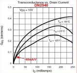
Check out Allen Wright's stuff; he uses a small FET on the bottom of his cascode circuits, a DN2540N5 on top should take care of the rest.
cheers,
Douglas
hey-Hey!!!,
I think it is troublesome to get high gm at low currents from high-current capable devices. For a small FET that is maxed out at 20 mA, half that will deliver reasonable gm.
cheers,
Douglas
Sure
") I'm having some trouble finding some mosfets that work at these currents believe it or not, RS seems to be listing all high voltage switching types. Even the little ones seem to be all 600V/0.5A types!
I'm having some trouble finding some mosfets that work at these currents believe it or not, RS seems to be listing all high voltage switching types. Even the little ones seem to be all 600V/0.5A types!Sure
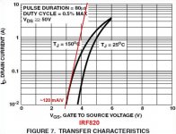
I found a datasheet for the IRF820 that goes down to 10mA...
I've been looking into this, looking for a low capacitance small signal device with high gfs at low current. It looks to me like the low current devices have relatively low gfs.
But I don't know why you say it won't work; what specifically is the problem? Even 40mA/V translates to 25 ohms Zo.
You could use a constant current sink if you're worried about the extreme of signal swing. That would tend to linearize the gfs.
Michael
Attachments
Guys,
Please remember that the critical parameter for a FET in voltage follower service is reverse transfer capacitance. A type with a low and stable reverse transfer capacitance is what the job requires.
There are a number of suitable types available. FWIW, I call for the ZVN0545A in low current situations and the IRFBC20 in medium and high current situations.
ZVN0545A Data Sheet
IRFBC20 Data Sheet
BTW, even a wimpy 12AX7 section has no problem in cleanly driving a ZVN0545A.
Just looked in Grey and Meyer's book. Two regions of gm variation exist for MosFets. For gate voltages above approx. Vthreshold+1 Volt, gm varies linearly with gate voltage and also as the SQRT(Id) [since Id = k1* Vg^2]. This is called the square law region.
Near threshold voltage (Vg = 0V up to about Vth +.5 V), gm varies linearly with Id, since Id = 10^(k2*Vg), ie exponential transfer like a bipolar. This is called the sub-threshold region or exponential region. This region occurs when the channel is cut off and substrate conduction effects are remaining.
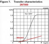
Michaels graph for the 2N7000 above illustrates the linear variation of gm with Vg with the large straight ramping section of the curve. The small curved section at low Vg is the sub-threshold region of gm variation, linear with Id [or exp(Vg)]. The flat horizontal section is in the saturation region.
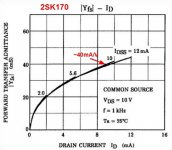
The graph for the 2SK170 illustrates the inverse parabolic variation [ie, SQRT(Id)] of gm versus Id. (Same as the linear gm variation versus Vg region for the 2N7000, but the 2SK170 graph here has an Id coordinate instead of Vg coordinate)
Near threshold voltage (Vg = 0V up to about Vth +.5 V), gm varies linearly with Id, since Id = 10^(k2*Vg), ie exponential transfer like a bipolar. This is called the sub-threshold region or exponential region. This region occurs when the channel is cut off and substrate conduction effects are remaining.
Michaels graph for the 2N7000 above illustrates the linear variation of gm with Vg with the large straight ramping section of the curve. The small curved section at low Vg is the sub-threshold region of gm variation, linear with Id [or exp(Vg)]. The flat horizontal section is in the saturation region.
The graph for the 2SK170 illustrates the inverse parabolic variation [ie, SQRT(Id)] of gm versus Id. (Same as the linear gm variation versus Vg region for the 2N7000, but the 2SK170 graph here has an Id coordinate instead of Vg coordinate)
Last edited:
I found a datasheet for the IRF820 that goes down to 10mA...
At 20mA the gfs of the irf820 looks to me more like 1900mA/V, as drawn by you. I know the actual value is a moot point; just saying.
At 20mA the gfs of the irf820 looks to me more like 1900mA/V, as drawn by you. I know the actual value is a moot point; just saying.
It looks like you are saying 1.9A/1V is the Gfs. The problem with this is you are evaluating on a log scale over several decades of current.
The quantity Gfs (also Yfs), like the analogous Gm for vacuum tubes is known as "dynamic transconductance" because it is a changing quantity evaluated at one particular point, in this case approximately 20 mA.
If you take the first 1/3 volt from the axis, you get approximately 40mA current delta for aproximately .33 V delta. This is how I estimated the Gfs for low current based on the slope of the line in a small region around the point of interest. Really the deltas ought to be made mathematically very small, which is defined by di/dv.
It's probably a stretch on my part to eyeball the first derivative of a curve on a log axis chart in the first place, but that's the general idea. Edit: I see this is probably the issue. I am making the same error as you in reading a straight line off a log scale, just smaller ;-)
Cheers,
Michael
Last edited:
- Status
- This old topic is closed. If you want to reopen this topic, contact a moderator using the "Report Post" button.
- Home
- Amplifiers
- Tubes / Valves
- Output impedance of various MOSFET followers at low (<10mA) currents