I am laying out a PP amp and I would like to direct couple the output from the first tube plate (6SN7) to the grid of the split load inverter (1/2 6CG7).
I can work out the voltages alright for bias but:
In calculating the gain of the first stage what do I use as the input impedance of the next stage without a grid load resistor?
Also, suggestion as to grid stopper value or is it even needed?
Plate voltage of the 6SN7 is about 79V and the cathode of the 6CG7 is at about 83V (-4V bias).
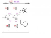
see unfinished - unchecked schematic attached
I can work out the voltages alright for bias but:
In calculating the gain of the first stage what do I use as the input impedance of the next stage without a grid load resistor?
Also, suggestion as to grid stopper value or is it even needed?
Plate voltage of the 6SN7 is about 79V and the cathode of the 6CG7 is at about 83V (-4V bias).
see unfinished - unchecked schematic attached
Attachments
In calculating the gain of the first stage what do I use as the input impedance of the next stage without a grid load resistor?
You can safely take it as "infinity". It's not, but it's not worth worrying about the actual value in the calculation, it will barely load down the previous stage. The effect on the value will be vastly swamped by component imperfection and drift.
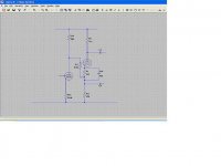
Why not add a cathode resistor between the cathode and lower 62K resistor to set the cathode current, a grid resistor from grid to the bottom of the cathode resistor where it meets the 62K resistor, and a bypass cap around the cathode resistor.
With these changes you can set the cathode current independently of the two phase resistors. This allows you to adjust it so you have 25% of your available voltage on each output resistor at the DC bias point. This maximizes your available voltage swing.
With these changes you can set the cathode current independently of the two phase resistors. This allows you to adjust it so you have 25% of your available voltage on each output resistor at the DC bias point. This maximizes your available voltage swing.
Attachments
Your numbers just don't add up. You have 2.6mA of current through the plate resistor of the second stage and 1.33mA through the cathode resistor. That defies the laws of physics and more specifically ohm's law.
Here's another way to approach this: make the current through the first two stages equal. In so doing you solve several problems. The first two stage will be exactly out of phase current wise so they can be fed by the same PS node. To make the two stages have equal current you will need the same tube for each stage (6SN7 and 6CG7 are close enough) and the combined cathode and plate resistors should add up to about the same value. That's why Willliamson used 47k and 22k although he did decouple the two stages. Another reason to use 22k is that the lower value resistors will give you better match plate to cathode. Use about 100V on the plate of the first tube with a 470ohm cathode resistor. Ip will be about 5mA and the stage will have a gain of almost 16. B+ will be about 340V.
Here's another way to approach this: make the current through the first two stages equal. In so doing you solve several problems. The first two stage will be exactly out of phase current wise so they can be fed by the same PS node. To make the two stages have equal current you will need the same tube for each stage (6SN7 and 6CG7 are close enough) and the combined cathode and plate resistors should add up to about the same value. That's why Willliamson used 47k and 22k although he did decouple the two stages. Another reason to use 22k is that the lower value resistors will give you better match plate to cathode. Use about 100V on the plate of the first tube with a 470ohm cathode resistor. Ip will be about 5mA and the stage will have a gain of almost 16. B+ will be about 340V.
I figured the"-" signs at the first tube were typo's, and the plate of the second tube was at 190V. That would come close to proper bias (-4V Grid to cathode on the second stage).
Although it would still leave the plate resistor with 65V across a 62K and 85V across the 62K Cathode resistor.
I dono......
Although it would still leave the plate resistor with 65V across a 62K and 85V across the 62K Cathode resistor.
I dono......
Sorry I wasn't more clear. No not feedback. Should have said plate of first tube to grid of second tube, then from grid of second tube to ground. Or run the plate of the first tube at 1/3 of B+ and couple plate to grid directly to get the voltages to work out correctly. Running the first tube at 1/3 B+ isnt always a suitable working point as far as symetrical voltage swing and distortion, but it achieves direct couple for dc and ac.If the first tube is run with 1/2 B+ then the second tube would end up biased with a very positive grid and a small voltage across the tube in order to get nearly 1/2 B+ across the lower and upper resistors, since half B+ is forced across the lower resistor because the grid is at that potential. Thus the need for the divider or lowering the plate voltage of the first tube.
Last edited:
Thanks everyone,
I had gotten myself all twisted up when I chose to use VR tubes to regulate the B+ for the input/driver section.
Let me explain my overall approach and maybe some suggestions might clear me up.
This amp is going to be a complete re-design using a chassis and components from a Zenith console. The original amp was 6BQ5 pentodes PP at VERY high B+ voltage and OP.
I decided that since I have a nice pair of smaller PP OPT's to replace the ugly and not so nice Zeniths that I would go with Triode strapping the 6BQ5's and since the chassis is about 18" x 18" I have room for additional tubes.
The original PS was woefully "dirty" NO filtering to the power tubes except an 80uF cap!
B+ was 430V
The "preamp" was off board in another chassis with all kinds of tone controls and a reverb tank along with a wild feedback setup that I want to scrap from the design.
The split load inverter is kind of a "signature" in the few PP amps I have built and I prefer to keep it rather than an LTP or other method.
Since the preamp was off board the need for an input tube came about to reach the final gain needed.
As I look it over again (back to the drawing board) I think I can coax enough gain from the first 6cg7 to suffice. This way I leave plenty of room in the chassis to use 3 VR tubes and regulate the B+ to a higher voltage (either 450,405,375,360).
One concern is to keep the Zout of the splitter low to avoid the miller on the Triode Strapped EL84's
I will go at it again today and post my ideas.
hi jerluwoo
The feedback you may encounter from this type of design particularly with triodes as I recall (from all the way back in the 70's = a 30+ year break from valve amps).
would be from the inversion control grid back to the plate anode of the 1st valve section.
It took all the way up to the 70's for any amps to sound good without stopper resistors or cup caps.(you have got the right type of inversion for it to work)
I just put feedback up as a possible problem as you can pull out a lot of hair trying to get them to sound good even if the maths is spot on.(valve construction, 2nd electrons, and stuff)
Yes Pointy I agree the devil is in the details as they say. Coldcathode your last circuit is probably overkill. Triode strapped el84's only need 10-12 volts rms for full output, at least thats what the datasheets say. Although you said you want the split load type pi I wouldn't discount using a long tail pair with a bjt or fet current source in the tail. The distortion sims Ive done have the split load comming in way behind the ltp setup. That really high B+ you have with the original is a combination of todays higher line voltage and that 80uF cap has probably lost a good bit of its capacitance because of its age, electrolytic drying out and such. Most supplies with cap input use the amount of capacitance to "tune" the voltage output, the higher the capacitance the lower the voltage output and vise versa.
Last edited:
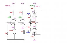
Does this look better?
No: you have the second tube biased -8v @200V with 4mA of plate current. This is not a operating parameter that fits on the plate curves i.e., it is a made up operating point not one based on the tube's parameters. See my first post. I gave you the correct parameters.
No: you have the second tube biased -8v @200V with 4mA of plate current. This is not a operating parameter that fits on the plate curves i.e., it is a made up operating point not one based on the tube's parameters. See my first post. I gave you the correct parameters.
- Status
- This old topic is closed. If you want to reopen this topic, contact a moderator using the "Report Post" button.
- Home
- Amplifiers
- Tubes / Valves
- Quick Question on Dc coupling