I'm building a sub miniature guitar amp built with 6021 tubes. I based the amp on the "Powerman" amp and added a cascode boost section a la the "Firefly" amp.
I wasn't able to really find anything on using 6021's in a cascode setup and I know just enough to be dangerous! Could someone point me in a direction of some information on how to design this stage properly?
I have been just taking some stabs in the dark on component values and its funtional but the sound is very rolled off and muddy. B+ is about 115 volts.
Thoughts comments suggestions?
Thanks
Tim
No mystery about cascodes. It's simply a two stage amp with a grounded cathode stage driving a grounded grid second stage. Like every other multi-stage amp, start from the end and work backwards.
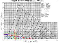
Here's how I designed a cascode. (Attached) Start with the second stage. In this case, assume a Vpp= 275Vdc, and play around with loadlines until an Rp= 68K gave the best compromise between THD estimate and output swing. (In this case, THD= 5.4%, which would be barely acceptable. 6BQ7s are hard to design for, having no audio pretenses whatsoever, and really require a higher Vpk to linear up. However, in this case, that THD estimate applies to just the one stage, not both. As with the solid state version, cascoding improves overall linearity. Also, this particular cascode was half of an LTP which nulls out even order harmonics, and if the THD is mostly h2, then you lose most of it anyway.) Next, use the plate characteristic to estimate u and g(m). From that, calculate r(p). You need to know that in order to figure out what your r(k) is likely to be. r(k) then becomes the plate load for the grounded cathode stage.
Next, run a loadline for the input stage. This is always a good idea to see if the first stage has enough swing to swing the output to its theoretical maximum. Here, we're OK in that regard, and good to go. No need to move the input loadline by adding external parallel resistance.
Finally, figure out what your point-to-DC ground voltages are. Then you're done. Build it to see if it really works as designed. In this case, it did, and measured results were within 5% of design nominal values.")
The A Number One bugaboo with cascodes is their eeeeeeeeenormous output impedance. Combined with the capacitances of a load, this will not play well at higher frequencies. After completing this cascode design, connecting the o'scope probe directly to the output gave results that looked positively hideous. A 1000Hz square wave had very tilted tops, the measured f(h)= ~20KHz. It looked like the slowest thing I'd ever built, either solid state or hollow state. This was, of course, an illusion caused by the capacitances of the scope probe, the connecting cable, and the Ci of the scope's vertical deflection amp.
Once connected to a cathode follower, the true picture emerged. The measured f(h)= 117KHz (-3.0db) and square waves had nice, flat tops with excellent rise and fall times, when the measurements were taken at the output of the cathode follower.
Here's how I designed a cascode. (Attached) Start with the second stage. In this case, assume a Vpp= 275Vdc, and play around with loadlines until an Rp= 68K gave the best compromise between THD estimate and output swing. (In this case, THD= 5.4%, which would be barely acceptable. 6BQ7s are hard to design for, having no audio pretenses whatsoever, and really require a higher Vpk to linear up. However, in this case, that THD estimate applies to just the one stage, not both. As with the solid state version, cascoding improves overall linearity. Also, this particular cascode was half of an LTP which nulls out even order harmonics, and if the THD is mostly h2, then you lose most of it anyway.) Next, use the plate characteristic to estimate u and g(m). From that, calculate r(p). You need to know that in order to figure out what your r(k) is likely to be. r(k) then becomes the plate load for the grounded cathode stage.
Next, run a loadline for the input stage. This is always a good idea to see if the first stage has enough swing to swing the output to its theoretical maximum. Here, we're OK in that regard, and good to go. No need to move the input loadline by adding external parallel resistance.
Finally, figure out what your point-to-DC ground voltages are. Then you're done. Build it to see if it really works as designed. In this case, it did, and measured results were within 5% of design nominal values.
I have been just taking some stabs in the dark on component values and its funtional but the sound is very rolled off and muddy. B+ is about 115 volts.
Thoughts comments suggestions?
The A Number One bugaboo with cascodes is their eeeeeeeeenormous output impedance. Combined with the capacitances of a load, this will not play well at higher frequencies. After completing this cascode design, connecting the o'scope probe directly to the output gave results that looked positively hideous. A 1000Hz square wave had very tilted tops, the measured f(h)= ~20KHz. It looked like the slowest thing I'd ever built, either solid state or hollow state. This was, of course, an illusion caused by the capacitances of the scope probe, the connecting cable, and the Ci of the scope's vertical deflection amp.
Once connected to a cathode follower, the true picture emerged. The measured f(h)= 117KHz (-3.0db) and square waves had nice, flat tops with excellent rise and fall times, when the measurements were taken at the output of the cathode follower.
Attachments
After completing this cascode design, connecting the o'scope probe directly to the output gave results that looked positively hideous. A 1000Hz square wave had very tilted tops, the measured f(h)= ~20KHz.
It's an extremely well known feature, a cascode amplifier without a load to drive, reverts to being just a class A amplifier without much else to recommend it, and with several quite other unpleasant side effects.
The whole topology is based around a known impedance to drive for it to act as any sort of SRPP (push pull amp).
Broskie explains this all rather well, but he has his own special takes on it.
This is a cascode this thread is discussing, not a SRPP, a whole 'nother animal. It actually has a lot to recommend it: much reduced CMiller, significantly higher voltage gain (u2 in theory; 4 -- 5 X u in practice) significantly reduced distortion since the variations in vpk is reduced. The cascode has all the features of a small signal pentode and avoids partition noise, and plate current "kinks" since no grid is positive WRT its corresponding cathode.
The only trade-off is that the output swing will be smaller than it would for a comparable single triode design. That may not even be a problem when driving pentode finals, but could be problematic if driving low-u triodes like the 300B, or low-u pseudotriodes.
The main problem I had was that there is very little to go on regarding hollow state cascodes as audio voltage amps while the main focus of the topology has long been RF. Cascodes are often seen as the front end preamps for TV tuners and FM xcvrs. In that capacity, the higher than normal rp is a plus since this reduces the loading on LC tuners, increasing selectivity.
The solid state version has long been used in solid state audio design, and for all the reasons listed above. I had to try and listen to see if hollow state cascodes weren't in use because it was "weird", or required an extra dual triode, another hole in the chassis, another heater to feed, or if it had been tried and rejected for poor sonic performance. I discovered it's as useful a topology for hollow state design as it is for solid state design. The hollow state cascode LTP performs very well indeed.
Then I came across an article in a 1956 edition of Wireless World that described the "Hedge Amp" which did indeed include a cascode LTP made from the Loctal version of the 6SN7 driving PP 1625s. It never made it to mass production.
There's lots of cutting and pasting going on here and the original poster didn't actually say much about his design.
Fact is, if you cascode 2 x 6021(a post from 6yrs ago!), you end up with quite low voltages across each valve,(1/2 a rather low supply v) which is not great for linearity.
The cascode stage you describe, my Dad used to describe as a "pentode" without all the disadvantages, inc the infamous microphony you got with EF86/6BS7/6BR7 and all that Mullard ilk.
- Status
- This old topic is closed. If you want to reopen this topic, contact a moderator using the "Report Post" button.
- Home
- Amplifiers
- Tubes / Valves
- 6021 Cascode