Hi all,
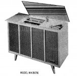
On one of my recent "garbage picking" trips I happened across an old Zenith Console (AM/FM,Phono)circa 1961. It barely fit in the trunk of the wifes Volvo but I got it home. This thing was 100% complete (owners manuals and all).
I had (3) options for it.
a: "Restore" it (clean it up, replace the grill cloth, re-bias, re-cap etc)BUT it is not a "pretty looking" thing and the wife didn't want it in the house.
b: Rip it apart for the OPT's and the PT for my 829B amp project.
c: Use the Amp section for my "Bi-amped" OB system project
I have pretty much decided on choice "C".
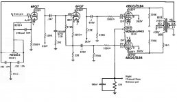
Attached is (1) channel of the power amp schematic cut out of the manual.
The "feedback" goes "off board" and thru the "presence" control as noted. I have a couple questions since "modifying" something existing is not my usual thing.
1: Any ideas on the effect of removing the feedback loop altogether?
(and if I did should I "lift" the grounded OPT tap?
2: Any suggestions as to the operating point of the tubes. ie can I get more power or less distortion at other points?
3: What purpose does the Cap and 73R resistor serve in the "hum balance" circuit?
4: Any idea why there is a 56R resistor in the Plate circuit of the bottom BQ5? The OPT has equal DCR on both sides?
Last but not least, assuming I only need about 5Watts, anyone with experience running the EL84 "Triode Strapped". Suggestions there?
Thanks,
On one of my recent "garbage picking" trips I happened across an old Zenith Console (AM/FM,Phono)circa 1961. It barely fit in the trunk of the wifes Volvo but I got it home. This thing was 100% complete (owners manuals and all).
I had (3) options for it.
a: "Restore" it (clean it up, replace the grill cloth, re-bias, re-cap etc)BUT it is not a "pretty looking" thing and the wife didn't want it in the house.
b: Rip it apart for the OPT's and the PT for my 829B amp project.
c: Use the Amp section for my "Bi-amped" OB system project
I have pretty much decided on choice "C".
Attached is (1) channel of the power amp schematic cut out of the manual.
The "feedback" goes "off board" and thru the "presence" control as noted. I have a couple questions since "modifying" something existing is not my usual thing.
1: Any ideas on the effect of removing the feedback loop altogether?
(and if I did should I "lift" the grounded OPT tap?
2: Any suggestions as to the operating point of the tubes. ie can I get more power or less distortion at other points?
3: What purpose does the Cap and 73R resistor serve in the "hum balance" circuit?
4: Any idea why there is a 56R resistor in the Plate circuit of the bottom BQ5? The OPT has equal DCR on both sides?
Last but not least, assuming I only need about 5Watts, anyone with experience running the EL84 "Triode Strapped". Suggestions there?
Thanks,
Attachments
.
3: What purpose does the Cap and 73R resistor serve in the "hum balance" circuit?
4: Any idea why there is a 56R resistor in the Plate circuit of the bottom BQ5? The OPT has equal DCR on both sides?,
Can only guess what the designer had in mind.....
3) I think so that there will be at least 73R when the wiper on the pot is at minimum. to prevent a direct connection to ground. The cap is common to both left and right, that is a clue that no audio signal goes through it. I think it is a filter to keep noise offthe top of that resistor. But why such a large value?
4) Maybe the phase inverter is not completely balanced and this helps compensate.
"Hum balance" is cathode bias and it's balance. If you improve a power supply you may call it "Idle currents' balance". One more option is to discard it, using LEDs for bias, like in SY's Red Light District.
I would discard "presence" control leaving feedback connected.
Resistor in anode is needed to prevent HF oscillations. Probably in case of different layout it would not be needed.
I would discard "presence" control leaving feedback connected.
Resistor in anode is needed to prevent HF oscillations. Probably in case of different layout it would not be needed.
Can only guess what the designer had in mind.....
3) I think so that there will be at least 73R when the wiper on the pot is at minimum. to prevent a direct connection to ground. The cap is common to both left and right, that is a clue that no audio signal goes through it. I think it is a filter to keep noise offthe top of that resistor. But why such a large value?
4) Maybe the phase inverter is not completely balanced and this helps compensate.
AHA

I looked it over and it appears that it is Biased for Class B operation.
Cathode Current about 15-17ma at idle.
The cathode of each tube "sees" about 87 Ohms. That gives me the -15 bias.
The large value of the cap is because it is a Rk bypass cap. Each tube seeing about 87R and 100uF gives me F3 of 18hz?
I am going to re-draw this and bias it ClassAB. I might even consider going Triode Strapped. I can live without the power if I get linearity and a little of the "Triode" sound.
Thanks.
Anyone else got some valuable .02 cents?
Last but not least, assuming I only need about 5Watts, anyone with experience running the EL84 "Triode Strapped". Suggestions there?
Thanks,
One of my favorite sounding tube amps is a PP EL84, based loosely on the topology of Eli Duttman/Jim McShane's "El Cheapo" circuit - triode strapped due to the lack of UL tap on the donor OPT.
Note that it's the topology of the CCS loaded LTP front end and P/P output section that counts here. In the case of our organ donor (Scott 222), it made more sense to use existing tube rectification and EL84 output tubes.
There's a very good reason that Eli/Jim chose the 12AT7 for the front end, as is outlined somewhere in the 60+ page thread.
http://www.audiophiletalk.com/cgi-bin/yabb2/YaBB.pl?num=1126228937
This was my first attempt at "re" building a P/P amp from scratch, and with help from the forum above, and most particularly Eddie Vaughn, it turned out very nice indeed (as in too good to risk cosmetic upgrades to the hacked up donor) . Biased for class A P/P triode, this is a big "about 5 watts" - makes my triode strapped Jolida EL34 sound muddy, dark and slow as molasses by comparison.
For anyone interested, read the entire thread, or contact Eli Duttman regarding the most recent evolutionary stage of the circuit maps.
An externally hosted image should be here but it was not working when we last tested it.
An externally hosted image should be here but it was not working when we last tested it.
An externally hosted image should be here but it was not working when we last tested it.
AHA
I looked it over and it appears that it is Biased for Class B operation.
Cathode Current about 15-17ma at idle.
No, it is class AB. Ratios of output transformers are bigger than usual as well, so EL84 tubes working with higher anode voltages, lower idle currents, sound better.
Good engineers with rich background designed this amp. Do you think novices can improve it turning into an ordinary amateur thingy?
Good engineers with rich background designed this amp. Do you think novices can improve it turning into an ordinary amateur thingy?
Yes! These good engineers designed this amp with keeping costs down as a major priority. But novices can use the best parts available and make it sound better and more reliable.
Yes! These good engineers designed this amp with keeping costs down as a major priority. But novices can use the best parts available and make it sound better and more reliable.
That's why I suggested to improve a power supply and bias scheme. But not to increase standing current when plate voltage is so high!
That engineers did not have modern LEDs and electrolytic capacitors, but they definitely knew about tubes and their regimes, right?
Do you see any differences?
No, it is class AB. Ratios of output transformers are bigger than usual as well, so EL84 tubes working with higher anode voltages, lower idle currents, sound better.
Good engineers with rich background designed this amp. Do you think novices can improve it turning into an ordinary amateur thingy?
WHOA!!
 I didn't think this thread would get so animated!! LOL
Wave,
I looked quick at a 6BQ5 curve and it looks to me like 40mA Plate current (250DCR in the primary and 10V drop). I can't find a curve with anything over 300V on G2 but I am guessing about 3.4 - 4mA per grid there. So you are correct in saying AB. As a "Novice" I was thinking in "triode mode" forgetting that the G2 current is also on the cathode. SO with roughly 43-44mA on each "half" of the "hum balance pot" we get ~2.2V then the 73R resistor gets 176mA (all four tubes) we get another ~12.8V HENCE the 15V Bias.
No matter how you slice it, I am really uncomfortable using that operating point considering tube life.
ALSO Engineers with a RICH BACKGROUND designed the TITANIC!!
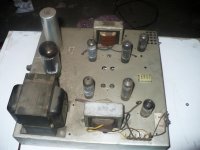
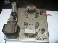
How bout some pics of the chassis and innards? Jeez....420V on the plates for a 6BQ5 seems awfully high, even for a 7189. With a 120VAC line, it's probably more like 450V! That's early 60's engineering for ya...push everything to the limit!
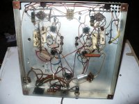
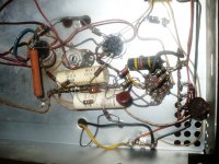
Pic's attached just as removed.
Attachments
So,
I am looking for some suggestions as to the following
A: Strap them as "Triodes"?
B: Lower the B+ and G2 voltage? 300V / 300V ??
Either way I intend to put a 6SN7 Input stage in the chassis where the connector was located along with RCA inputs there.
I will also add a volume pot after the SN7'.
Aesthetically I think I will strip it down and paint the chassis and add some nice wood corners/legs. Replace the sockets with Teflon or Ceramic along with better caps & resistors.
Still considering TS or Pentode?
ALSO Engineers with a RICH BACKGROUND designed the TITANIC!!
Then the captain drove it into an iceberg
A: Strap them as "Triodes"?
B: Lower the B+ and G2 voltage? 300V / 300V ??
C: buy new output transformers.
Then the captain drove it into an iceberg
After that engineers designed Queen Mary placing around more of motor boats than needed co carry the crew and passengers.
It still alive, here in California, serves as a museum and a fashionable hotel.
So, if to go with different power and output transformers, what the reason to damage this one existed amp, if better PS and bias scheme can improve it significantly? To reuse a chassis drilling new holes in it?
Then the captain drove it into an iceberg
ACTUALLY!! It is fairly well known that the Chief Engineer told the captain NOT TO SLOW DOWN!! His ship was unsinkable and setting a speed record was more important than safety!
C: buy new output transformers.
Wave, why do you say that? Are these suspect? They are fairly beefy albeit not of the highest quality. What would you suggest?
On a side note: I had listened to this before pulling it apart. (it actually had stereo tape inputs). The sound was "OK" but it also has a "Reverb Tank" (nice piece from Hammond) in the preamp that you could not take out so I was not really impressed.
After that engineers designed Queen Mary placing around more of motor boats than needed co carry the crew and passengers.
It still alive, here in California, serves as a museum and a fashionable hotel.
So, if to go with different power and output transformers, what the reason to damage this one existed amp, if better PS and bias scheme can improve it significantly? To reuse a chassis drilling new holes in it?
Wave,
Heres the scenario:
A: The console is UGLY so no real value in it as a complete unit.
B: The Phono section is MONO and not very good
C: The preamp section includes that reverb circuit which might be nice for a GHEETAR amp but not in my system.
D: The amp cannot function alone without modifications to the chassis.
Those factors lead me to where I'm at.
Do I completely gut the thing and redesign it altogether?
OR
make some minor mods to the the operating point (or triode strap it) and add the input tube.
The connector as shown in the picture can be removed and a hole rounded out for the octal socket for the 6SN7 input. Drill a couple more holes for RCA jacks and the volume pot and away we go!
Attachments
Then the captain drove it into an iceberg
OK, then engineers with a rich background designed the Eastland, of relevance here a) because the engineering problems leading to the disaster were likely due to "corrections" made after the Titanic sank, and b) because many passengers who lost their lives on the Eastland were employees and their families from Western Electric.
- Status
- This old topic is closed. If you want to reopen this topic, contact a moderator using the "Report Post" button.
- Home
- Amplifiers
- Tubes / Valves
- Decent Junk Pile find! Need Advice suggestions etc.!