I've read that a little plate glow is ok as long as it doesn't "runaway"
I just purchased two new sets of tubes (6l6GC coke bottle chinese) and JJKT77) Both exhibit plate glow that is almost the entire crease in the winged part of the plate (very narrow but vertically long).
How long do you wait to see if it runs away? If it's going to happen does it happen within an hour (hasn't )
I have a simple se with the largest selectable cathode resistor being 680 ohms. (no problems highest setting-460ohms with JJel34 or JJKT88)
I can see the heater glowing thru the plate holes no problem But where do I look for the screen to see if its glowing too.
I've read many posts about people worried about and checking for this.
Thanks Paul
You don't want any amount of red glow on the plates. If it is hot enough to emit visible light, then it is hot enough to boil out the trace gases dissolved in the metal. It will slowly contaminate the vacuum and ruin the tube.
The screens can only be inspected if there are holes in the plate somewhere. I've seen Chinese tubes with solid plates, so there is no easy way to see the screens. Here's a photo of a Russian tube with plate holes. You might be able to see two spots of glowing screen grid through the upper hole, and one spot through the lower hole.
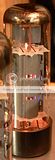
http://i69.photobucket.com/albums/i43/Ty_Bower/Tubes/hotscreen.jpg
The screens can only be inspected if there are holes in the plate somewhere. I've seen Chinese tubes with solid plates, so there is no easy way to see the screens. Here's a photo of a Russian tube with plate holes. You might be able to see two spots of glowing screen grid through the upper hole, and one spot through the lower hole.
http://i69.photobucket.com/albums/i43/Ty_Bower/Tubes/hotscreen.jpg
Those Chinese 6L6's only have a dissipation rating of 19 watts. For the JJ KT77, I wouldn't go higher than 25 watts. Do you know ohm's law? How much voltage is across that 680 resistor? Divide that measurement by 680. That's the cathode current. What's the plate voltage? Multiply that number by the cathode current and you will get a quick and dirty way to find the tube dissipation.
Measured voltage across R 13 &23 = 3 V rechecked this 3V again.
This is where to measure plate current right?
Measured voltage across R17 &27 = 36 V Cathode current assuming 680 ohms is 36 V.
I have actually loooooked! cant find anywhere where it actually tells how to measure B+ voltage (except some guitar amps sites that sounds different enough from my simple se that I was fraid of doin' it.
To measure B+ with the tubes in and one probe clipped to the ground could I connect the other probe to the piece of the tube socket sticking thru the bottom of the board?
Plate current should be measured across R13 or R23 right?
How can B+ be reduced?
Gu-50 tubes have nickel alloy plates to sustain accidental glow, but 6L6GC are not designed for such an abuse. It is the first time I hear such a rumor Pavel; however Internet is big and there are lots of evil jokes there, I've opened a topic recently about claims of increased gas mileage by acetone, as an example.
I have actually loooooked! cant find anywhere where it actually tells how to measure B+ voltage.....To measure B+ with the tubes in and one probe clipped to the ground could I connect the other probe to the piece of the tube socket sticking thru the bottom of the board?
To measure the B+ in a Simple SE you clip one probe on ground, and the other can be connected to either the choke terminal closest to the back of the board, or the wire on R1 closest to the back of the board, or the red wire on either output transformer, or the wire on R4 that is right on the rear edge of the board. These are all the same electrical point, measure whichever is easiest to get to.
Plate current should be measured across R13 or R23 right?
That will tell you the plate current for the 12AT7. You want the current through the output tubes, which you already have! The plate current by itself is not too easy to measure. The cathode current and the plate voltage will allow you to figure the total (plate and screen) tube dissipation.
You know that the cathode voltage is 36 volts. You know that the cathode resistor is 680 ohms. Ohms law says that the cathode current is 680 ohms divided by 36 volts or .053 amps, which is 53 mA.
Now to figure out how much power is being dissipated (burned up as heat) in the output tube, we need to know the actual voltage across the tube. We need another piece of information, the plate voltage. It can be measured (one probe on ground, the other on the plate lead from either OPT which is usually blue), or guessed from the B+ voltage. I am going to explain how to figure this out using typical Simple SE measurements, If your actual numbers are somewhat different, substitute them and recalculate.
The average Simple SE has a B+ voltage of about 440 volts with a 5AR4 rectifier. The typical OPT will lose about 10 volts due to losses in the wire inside it. This will make the plate voltage about 430 volts. You have already measured the cathode voltage at 36 volts. This means the tube has 430 - 36 = 394 volts from plate to cathode. To figure the tube dissipation you multiply the 394 volts by the .053 amps (from the calculations above) to get 20.9 watts. A 6L6GC tube is rated for 30 watts of plate dissipation, so it should not glow in this application.
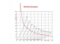
I have cranked the old Chinese Coke Bottle 6L6GC's up to 30 watts and well beyond. There is no glow at 27 watts and a faint glow can barely be seen in a dark room at 30 watts. There is a picture on this forum somewhere of those tubes running at 44 watts, and yes they were glowing brightly. I have had different results with some of the newer Coke bottle and round 6L6GC's, and some of them begin to glow with less than 30 watts applied to them.
What can be done to cool the tubes, well the dissipation must be reduced. This can be done by reducing the tube (or B+) voltage, or reducing the tube current. The easiest way to do both is to use a larger value of cathode resistor. This will lower the tube current and raise the cathode voltage a few volts. The B+ voltage can be lowered by using a 5U4 instead of a 5AR4 for the rectifier tube.
pforeman,
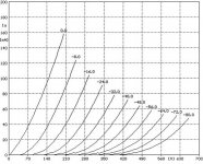
It looks like you are at 53mA Cathode current w/Bias of -36V, according to the curves I have for a 6L6 that puts your plate voltage at about 380V.
So Power (watts) = I(current) X E(volts) or 380 x .053 = 20 watts just above the rated dissipation for that tube.
Now that is just a guess. Best bet is to measure the voltage at the Plate Terminal.
Plate terminal is #3, check DCV to ground. Do you have a set of curves and datasheet for those tubes?
post them if you do.
Yes I have RCA Reciveiving Tube Manual
I am talking about the 6L6GC coke bottle.
I added 100 ohms to the resistor installed on the board.
The values now are (by way of bias selector switch and directly measured)
752,652,628,617,600,500 (ohms)
B+ 459 V
Plate 452 V
Cathode current 55 mA
I get no red plate syndrome now on the highest setting only for the KT77 or the 6L6GC ( never had the problem with the JJEL34 or the JJ KT88.
When looking at the recieving manual for the 6L6GC I see several columns.
Class A1 amplifier, Class A1 amplifier Triode connected, Push Pull Class A1 amplifier...AB1
If I look at the triode connected column, the design maximum is 450 Vp,
and 30 watts plate dissipation.
I should have been under 30 watts, even with my previous cathode resistors,
is it the 2 v. over plate that would cause the plate to glow?
Thanks
Paul
Paul,
Just a few tips from a well seasoned "beginner/novice".
1: As I saw in someones profile quote, and I paraphrase a little "I.C.'s have specifications - Tubes have GUIDELINES!" The 2 volts over on Plate voltage is not the issue, the 53mA is not the issue. The real issue is the 24 Watts of Plate dissipation. (I'll explain in tip #2)
2: Using the RCA manual is nice, BUT, it is probably 40 year old information. This is based upon production samples taken from RCA lines, and tested on AVERAGE. You have tubes produced recently with typically "substandard" materials in China. (I have experience in other industries with Chinese manufacturing and it is from experience rather than racist paranoia that I say Chinese stuff is substandard). Someone posted that the chinese 6L6's have a max dissipation of 19Watts. If so that would explain why you are getting "glow" at 24-25 Watts of Dis. If you were given a datasheet with those tubes check it out there.
3: "read between the lines" Tubelab is a VERY intelligent, creative designer and has contributed greatly to the hobby. But, look at his own profile quote,
"Too much power is almost enough! Turn it up till it explodes - then back up just a little"
This should tell you he likes to "push" his tubes. That is something you may or may not prefer to do. It is personal preference, one of the things that makes me like this hobby so much is the many ways to get to the same ends.
4: The JJ tubes are probably made with a much better quality materials and the design of the EL34 and KT88's inherently have higher dissipation ratings.
All in all I would check the dissipation ratings of the tubes from manufacturers data rather than old manuals.
Like tube lab says increasing the cathode resistor is the easiest way to go. But overall you have a pretty high B+ and low DCR in the OPT's so maybe a rectifier tube change is a good idea.
One more thing.
Learn and memorize Ohm's law backwards and forwards along with all it's permutations. Also, watts law.
Electricity follows these laws ABSOLUTELY. So, because of the "algebra" involved many SMALL changes can result in BIG changes to the output.
example; if a "guideline" for a Power Transformer is 700 to 800 V's Center Tapped and you choose an 800 Volt unit.
Then the OPT DCR is say 130 ohms (like yours) but the range the designer used is more like 175-220 ohms. Then you would get a Plate voltage at 50mA cathode current of say 530 Volts
Use a Power Transformer of 700VCT and a OPT with 220 Ohms DCR with the same rectifier and 50mA of cathode current and plate voltage would be about 454 Volts.
A change of almost 80V with only a change of 50V on the supply and a DCR change of only 90 ohms. The DCR change only would result in a change of 6 volts.
So you see variations of the components can "stack" and change the results by a large margin.
Good luck
3: "read between the lines" Tubelab is a VERY intelligent, creative designer and has contributed greatly to the hobby. But, look at his own profile quote,
"Too much power is almost enough! Turn it up till it explodes - then back up just a little"
This should tell you he likes to "push" his tubes.
Yes, I plead guilty. I do often push MY tubes, and usually only ones that are cheap or free. $1 sweep tubes and hamfest cheapies get "tested".
I also spec a reasonable operating point for my designs that are intended for use by others. As I have stated on this forum and on my web site, operating any "receiving tube" in the "red zone" will shorten its life and may lead to catastrophic failure. Some transmiting tubes are designed to be operated with a red plate, but not any of the tubes used in my boards.
It is well known that an SE amp requires a fairly hot operating point. The customary choice for most SE amplifiers is 80 to 90% of rated tube dissipation. Any tube sold as a 6L6GC should be capable of 30 watts of plate dissipation WITHOUT red plate. The target dissipation for the 6L6GC in the Simple SE was 25 watts which is in the 80 to 90% range. At the time that I designed the Simple SE I collected a large sample of old tubes (NOS and used), and bought several examples of new production tubes. The amp was tested with all of these tubes and the choice of a 560 ohm cathode resistor was valid at the time the amplifier was designed.
A few things have happened since the Simple SE that may require a different value resistor.
The largest change has been the ever escalating line voltages, the increased distortion present on our power lines, and the increase in output voltage from most power transformers especially Hammonds. These have all contributed to a considerably higher B+ voltage than what I was getting when I designed the amp. When I built the first Simple SE and tested all of those tubes I was getting 438 volts of B+, now pforeman is measuring 459 volts.
You have tubes produced recently with typically "substandard" materials in China.....Someone posted that the chinese 6L6's have a max dissipation of 19Watts.
It is also apparent that the quality of the recent production Chinese tubes isn't what it used to be. I tested 8 different Chinese Coke Bottle 6L6GC's back when I designed the Simple SE. They were all useable at 30 watts of dissipation. I took one very used pair and tested them from 30 to 44 watts in 2 watt steps. This is clearly not the case with the new stuff if some of them glow at 24 watts. I have never seen any published data on Shuguang tubes other than some early data sheets that were obviously lifted from the old RCA data.
There are some creative relablers out there too that sell stuff (primarilly Russian) as 6L6GC's that are not capable of dealing with 30 watts, but there are some serious Russian tubes out there that can handle over 30 watts.
I have explained this several times on this forum, but I have not had the time to update the web site. I am working on updating the site, but life has thrown several curves at me lately.
I just have a question about the "catastrophic failure" part. If I say "what the h..." these chinese tubes were $7.50 a piece. I'll just play them 'til catastrophic failure, will it do more than blow a fuse, or ...
Because, man I think they sound great!
After that, I really like the sound of the other tubes (KT88 and EL34) and have no problems with plate glow, so I'll just stick to them, or maybe invest in better 6l6GC's .
Thanks
Because, man I think they sound great!
After that, I really like the sound of the other tubes (KT88 and EL34) and have no problems with plate glow, so I'll just stick to them, or maybe invest in better 6l6GC's .
Thanks
I just have a question about the "catastrophic failure" part.
I have stated several times that if you are going to push a tube into the red zone you must check carefully for a glowing screen grid. I have stated that a glowing grid is much worse than a glowing plate. Why?
A glowing grid on a tube that is being operated within its specifications usually means poor assembly quality. Ideally the grid to cathode spacing should be constant over its entire length. When it is not (usually due to bent grid rods) there will be hot spots on the grid and possibly the plate. This means that the majority of the tubes current is flowing in a localized area, which can lead to runaway, and a tube arc. If one or two grid wires gets hot enough to melt or warp a direct short can happen. It is hard or impossible to see the screen grid on the Chinese 6L6GC's, but I have yet to find one of these tubes with a glowing grid despite some very extreme over the limit tests. EL34's on the other hand have a propensity for grid glow.
A very hot (bright red to white hot) plate will eventually cause the glass to fail due to melting or cracking. This type of failure usually does not cause amp damage. A mildly glowing plate will not usually lead to immediate catastrophic failure. It does (as previously stated) lead to contamination of the vacuum in the tube. As the vacuum in the tube degrades (the tube becomes gassy) a conduction path through the ionized "gas" develops. This will cause distortion, and increased tube current. The increased tube current leads to more heat (the red gets brighter) which creates more gas. This cycle can lead to eventual runaway.
What can happen to the amp when the glowing tube fails? Usually the amp will tell you that something is wrong (it sounds bad) long before catastrophic failure occurs. If you ignore that, or happen across a poorly constructed tube that shorts out (can happen to a non glowing tube too) there will be a sharp increase in tube current. This usually will just blow the fuse (if the fuse is the right size). It is possible that the rectifier tube could be damaged and also possible that the cathode bypass capacitor could be damaged.
The cathode voltage is an indicator of the tube current. Whenever I "test" tubes in the red zone I keep a voltmeter connected to the cathode. If the voltage finds its happy spot after 10 minutes or so of operation and remains constant after a long listening session, tube runaway is not likely. If the voltage slowly creeps upward, I would be wary of operating the tubes at this level. Assuming stable operation, write down the numbers and check them every few weeks. If they don't change, replace the tubes when they start to sound bad. The Chinese 6L6GC's that I have been using seem stable after a few years of repeated excursions into the red zone, but they are about 6 years old. I don't have much experience with their new ones, since I haven't killed any of my old ones yet.
I found a box full of poorly constructed Sylvania (yes, American made Sylvanias) 6V6GT's. These came from military stock too. Over half of these have gone gassy just sitting on the shelf. I purposefully stuck some into a Simple SE just to see what would happen. Yes, I knew that they would blow up. I did eventually kill a cathode cap. These "experiments" and the pictures of the eminent failure can be found here:
http://www.diyaudio.com/forums/showthread.php?t=124527&highlight=death+simple
- Status
- This old topic is closed. If you want to reopen this topic, contact a moderator using the "Report Post" button.
- Home
- Amplifiers
- Tubes / Valves
- Red Plate,Tube runaway, glowing screen grids