
(repeating my last post - as it could not be from some wierd reason edited nor deleted)
hi all,
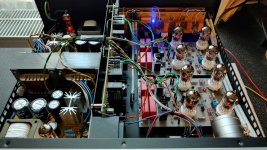
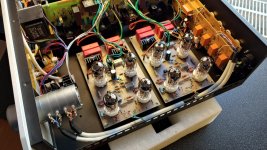
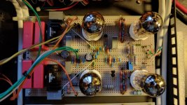
so finally here is my build - aka RTP3C, line stage only, with IRF820 at output stage bootstrap instead 5-th tube.
the case is some Aliexpress Reisong/marantz7 model, I had to bought 2pcs at past, so I have used its power supplies and input switching PCBs.
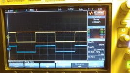
good news is, after assembly it still keeps about 1MHz bandwith (scope blue=input, yellow=output @20kHz) - it sounds really nice.
> thanx Allen <
hi all,
so finally here is my build - aka RTP3C, line stage only, with IRF820 at output stage bootstrap instead 5-th tube.
the case is some Aliexpress Reisong/marantz7 model, I had to bought 2pcs at past, so I have used its power supplies and input switching PCBs.
good news is, after assembly it still keeps about 1MHz bandwith (scope blue=input, yellow=output @20kHz) - it sounds really nice.
> thanx Allen <
Attachments

Last edited:
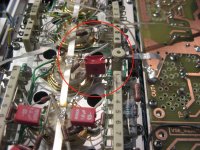
...Note the 47K resistor encircled in red, which was Allen's solution to deal with the high gate capacitance of the MOSFET. The use of IRF710 here is that it has lower gate capacitance than what we used initially IRF820.....
.
concerning the resistor, using IRF820 it rings at about 5Mhz for few uSec. resistor value <10k causes stable oscillating, value at my case >82-100k behaves fine.
(repeating my last post - as it could not be from some wierd reason edited nor deleted)
hi all,
so finally here is my build - aka RTP3C, line stage only, with IRF820 at output stage bootstrap instead 5-th tube.
the case is some Aliexpress Reisong/marantz7 model, I had to bought 2pcs at past, so I have used its power supplies and input switching PCBs.
good news is, after assembly it still keeps about 1MHz bandwith (scope blue=input, yellow=output @20kHz) - it sounds really nice.
> thanx Allen <
Looks great!
Alex
Hi perys,(repeating my last post - as it could not be from some wierd reason edited nor deleted)
hi all,
so finally here is my build - aka RTP3C, line stage only, with IRF820 at output stage bootstrap instead 5-th tube.
the case is some Aliexpress Reisong/marantz7 model, I had to bought 2pcs at past, so I have used its power supplies and input switching PCBs.
good news is, after assembly it still keeps about 1MHz bandwith (scope blue=input, yellow=output @20kHz) - it sounds really nice.
thanx Allen <
Quite some time ago that I was here in these very turbulent times in this world.
I would agree with what Alex said, looks great indeed, although I do not understand why you didn't implement the phono stage as well since your setup makes also use of an analog rig as I see and then it would definitely have made sense I think. But ok, your decision of course.
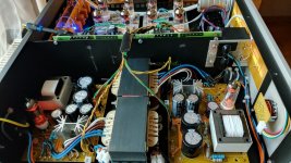
Looking at the first image showing the inside I noticed that you have made two completely separate HV supplies for each channel at the left hand side looking also very impressive. As can be seen they make use of tube rectifiers, wow! Could you tell something more in technical detail how you realized these?
As you may know the original doesn't make use of two separate HV power supplies because Allen Wright didn't find that necessary due to his HV super regs for each channel with their use of constant current sources between PS and regulator. These make sure that there is extremely high isolation from the power supply as there is always only a large DC and as good as no AC current flowing and as such crosstalk from channel to channel due to the power supply shouldn't be an issue. This quite in contrast what would be the case when using series regs for voltage regulation I think.
If I see it right you make use of these HV super regs as well noticing the two PCB's in upright position between PS and line stage circuits.
So a bit of an overkill I'm asking myself?
Kind regards,
Günter
I have always used dual mono power supplies - partly because it strikes me as good practice (and with a separate PSU box I don't see any reason not to), but partly so as to simplify the signal ground arrangements.
I am intrigued that you replace one of the valves in each SLCF, but add a valve rectifier in the PSU. The only reason I would do the latter is to ensure a slow ramp-up of the HT voltage - any other performance advantages would be neutralised by the chokes and the shunt regulation. Allen said he was convinced the all-valve SLCF sounded the best - he told me that if you wanted to replace one of the valves with a MOSFET you would sacrifice less if you used it for the constant current sink on the cathode than if you used it in the bootstrap circuit.
Anyway, the essentials of Allen's design are still there (apart from the phono stage!), and I am sure your RTP3 still sounds terrific.
Alex
Hi perys,
Quite some time ago that I was here in these very turbulent times in this world.
I would agree with what Alex said, looks great indeed, although I do not understand why you didn't implement the phono stage as well since your setup makes also use of an analog rig as I see and then it would definitely have made sense I think. But ok, your decision of course.
Looking at the first image showing the inside I noticed that you have made two completely separate HV supplies for each channel at the left hand side looking also very impressive. As can be seen they make use of tube rectifiers, wow! Could you tell something more in technical detail how you realized these?
As you may know the original doesn't make use of two separate HV power supplies because Allen Wright didn't find that necessary due to his HV super regs for each channel with their use of constant current sources between PS and regulator. These make sure that there is extremely high isolation from the power supply as there is always only a large DC and as good as no AC current flowing and as such crosstalk from channel to channel due to the power supply shouldn't be an issue. This quite in contrast what would be the case when using series regs for voltage regulation I think.
If I see it right you make use of these HV super regs as well noticing the two PCB's in upright position between PS and line stage circuits.
So a bit of an overkill I'm asking myself?
Kind regards,
Günter
Hi Günter,
thank you for your interrest. There are few shortcommings at my design. Few are by concept, other by necessity
")
Regarding phono stage - I have started with my phono/vinyl career at about Jan/Feb 2021, really from zero. I had a lot experiences from CD world, HiFi and AV shows etc., but I have no any vinyl record and no one close to me who would be a vinyl-hifist. Because I must buy-back a turntable from one of my installations due to prolonged guarantee service during covid lockdown restrictions, and I started to find a way how to go ahead step by step with my AV setup - sure, with only tubes allowed...
So I found some phono-preamp at Ali and ordered it, but the seller told afterwards this product is no longer available and I have to buy something else. Thus I bought 2 Reisong line-preamps (aka Marantz 7 inside) with aim tat I will build my own phono-stage into one of the units - which I did, again, using one of Ali kits. Meantime, I get my first few vinyls and I was playing couple of months by this my-phono-preamp and Reisong aka-marantz7 preamp.
Then I was seeking about some nice and ideally sharp-edge preamp instead aka-marantz7, and I first time found VS-RTP3. By the schematics found at VS webpage I decided to buy a final product, aimed for unbalanced SVP2 at that time (as my monoblocks are also unbalanced only). Nevertheless I did not find any available unit (even used) for sale, so I decided to go for RTP3 build into Reisong replacing internal aka-marantz7 circuitry.
Finally, two the-same Reisong units at my AV setup I found is to be "overkill" impressive
Now to your questions:
- phono stage was already running at one of Reisong chassis, thus I need only line-preamp.
- from both Reisong units I have 2 power transformers and two HV-supplies with choke/valve-rectifier. Both with relative proper B+ voltages, but only about 50mA capability, so I have to use both.
- I then bought (April/May 2021) at VS pair of Super-Regs (and both great and lovely Cook-books - because it was some space inside the chassis for both and I like my AV set full-house equipped Then I set my RTP circuitry version related to Allen's advices, but with only line stage and FET instead of 5.tube due to limited HV (B+) supply given by mentioned HV supplies.
- both Super-Regs are running only with limited HV CS-headroom (max 20V) and small shunt current (about 10-15mA). On the other hand, when I finally compared sound with/without Super-Reg's CS part bypasswed, i found minimal noise/ripple and sound qualty impact, I guess due to valve/choke at HV-power supplies. basically, at this setup wpulc be only shunt regs fine, nevertheless i have 2 Super-regs and thus are built-in.
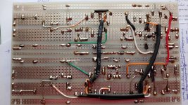
- both line-channels are build onto universal drilled PCB's, with using 2 the same input-switch boards from aka-marantz7, and there is some compromise again - it is not one board for L and second for R, but one for L/R-inverting) and second for L/R-noninverting balanced inputs pins
- my final RTP circuit version leaves FET bootsrap UNused, as it causes oscillations due to different swing spped tube vs. fet; thus it achieves bandwith "only" 1MHz or slightly above, which is about hlaf compared to if fet would be used (by simulations), nevertheless even with good stability achieved with fet, it runs upto about 1.5MHz but sound was not so liquid as with fet disconnected.
Some pics and addditional info about my Per-Jadis monoblocks could be seen at my website: "https://perys.cz/hobby/lampamp-per-jadis-ja30-mk2022/"
Jiri
Attachments

Hi Alex,I have always used dual mono power supplies - partly because it strikes me as good practice (and with a separate PSU box I don't see any reason not to), but partly so as to simplify the signal ground arrangements.
I am intrigued that you replace one of the valves in each SLCF, but add a valve rectifier in the PSU. The only reason I would do the latter is to ensure a slow ramp-up of the HT voltage - any other performance advantages would be neutralised by the chokes and the shunt regulation. Allen said he was convinced the all-valve SLCF sounded the best - he told me that if you wanted to replace one of the valves with a MOSFET you would sacrifice less if you used it for the constant current sink on the cathode than if you used it in the bootstrap circuit.
Anyway, the essentials of Allen's design are still there (apart from the phono stage!), and I am sure your RTP3 still sounds terrific.
Alex
yes, this is it: "The only reason I would do the latter is to ensure a slow ramp-up of the HT voltage.."
The HV slow ramping up is very convenient and goes with moreless the same speed as ECC88 tubes heats itself - nice and elegant.
Jiri
Hi Jiri,
Thanks for anwering.
Regarding your problems with oscillations. Did you apply 100R grid stoppers in your line stage circuit as shown in the schematic on the website?
Then it might be a good idea to increase value to 330 Ohm as Thomas from Vacuumstate suggested here under #528 or maybe even higher up to 1k as often seen with E88CC tubes in other schematics. And you also should solder these grid stoppers directly to the corresponding pins of the tube sockets in order to keep this connection path from resistor to pin as short as possible.
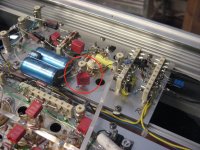
Other possible measure that could be done in order to tame oscillations if coming from the SRegs is to add a 0.10 uF film cap at the HV entrance on each of the line stage boards with the other side of the cap connected to ground. This in order to form a short path to gound for HF. I got this information in the past from another member here in this thread who had also reported problems with oscillations and this method had stopped oscillations completely as he told me.
Here you can see it encircled in red as implemented on the line stage and phono metal boards from a VS RTP3 kit:
Regards,
Günter
Thanks for anwering.
Regarding your problems with oscillations. Did you apply 100R grid stoppers in your line stage circuit as shown in the schematic on the website?
Then it might be a good idea to increase value to 330 Ohm as Thomas from Vacuumstate suggested here under #528 or maybe even higher up to 1k as often seen with E88CC tubes in other schematics. And you also should solder these grid stoppers directly to the corresponding pins of the tube sockets in order to keep this connection path from resistor to pin as short as possible.
Other possible measure that could be done in order to tame oscillations if coming from the SRegs is to add a 0.10 uF film cap at the HV entrance on each of the line stage boards with the other side of the cap connected to ground. This in order to form a short path to gound for HF. I got this information in the past from another member here in this thread who had also reported problems with oscillations and this method had stopped oscillations completely as he told me.
Here you can see it encircled in red as implemented on the line stage and phono metal boards from a VS RTP3 kit:
Regards,
Günter
Attachments
Last edited:
Hi Jiri,
Thanks for anwering.
Regarding your problems with oscillations. Did you apply 100R grid stoppers in your line stage circuit as shown in the schematic on the website?
Then it might be a good idea to increase value to 330 Ohm as Thomas from Vacuumstate suggested here under #528 or maybe even higher up to 1k as often seen with E88CC tubes in other schematics. And you also should solder these grid stoppers directly to the corresponding pins of the tube sockets in order to keep this connection path from resistor to pin as short as possible.
Other possible measure that could be done in order to tame oscillations if coming from the SRegs is to add a 0.10 uF film cap at the HV entrance on each of the line stage boards with the other side of the cap connected to ground. This in order to form a short path to gound for HF. I got this information in the past from another member here in this thread who had also reported problems with oscillations and this method had stopped oscillations completely as he told me.
Here you can see it encircled in red as implemented on the line stage and phono metal boards from a VS RTP3 kit:
Regards,
Günter
Hi Günter,
I have used 150R grid stoppers from beginning - but oscillations or ringing arisen only if FET bootstrap was used.
As I wrote above concerning the FET, I used irf820 and signal driving resistor has to be more than approx 100k to stop ringing - but such solution may be do not oscilate at result, but the source of oscillation is still there, only dumped/covered at its behaviour. Therefore I finally disconnect this driving resistor to FET's gate (means leaving FET inactive and fully openned at supply current path) and accept "only" 1MHz bandwith.
Without this FET bootstrap it behaves inherently stable, even if I tested grid stoppers ommited,.. I checked also value 1k, it seems to me with no any impact to stability or sound quality, so now are 150R resistors used here.
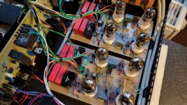
Blocking Cap I have here as well, but theese I add some time after when replacing JJ tubes with NOS Tesla -just to try sound impact (bass definition..) - as i mean it as good practice at every electronic device. I compared connection theese Caps either cascode-stage or SLCF stage.... between at PCB is only let say 40mm wire... and I found out that connection at cascode-stage makes sound little harsh, which surprised me a bit
so finalyy is at is supposed to be, connected to SLCF stage - it could be seen at pics (orange wires are HV, green GND, the Caps are gray cubes).Just for your information, as here are not point-to-point soldering but universal PCBs, I try to keep all connections (sure namelly signal ones) as short as possible (the black insulated pairs are heaters supplies) and also here could be seen how layout itself was born
Jiri
Attachments
Last edited:
Hi Jiri,
Sounds all very strange to me.
If you ask me my advice would be say goodbuy to the FET for the bootstrap and take a tube in this position.
This was also Allen Wright's preferred solution for the RTP3C and now D/E from a sonical point of view and I can't remember ever having heard from
a member here having problems with this solution like the ones you describe here.
Kind regards,
Günter
Hi Günter,Hi Jiri,
Sounds all very strange to me.
If you ask me my advice would be say goodbuy to the FET for the bootstrap and take a tube in this position.
This was also Allen Wright's preferred solution for the RTP3C and now D/E from a sonical point of view and I can't remember ever having heard from
a member here having problems with this solution like the ones you describe here.
Kind regards,
Günter
yes I catch Allen's remark that all-tube solution sounds best...
so may be at my next RTP build
thanx, Jiri
Since this topic is about several VS preamps I hope it's alright to ask a question aout the FVP5 revision 1.
A 47K resistor to ground (#1) was added to the gain stage's anode to reduce gain to 5x. How does this work?
And also I'd like to lower the gain more, I guess a bigger resistor would do that job, but I'm uncertain about the value.
Thanks.

A 47K resistor to ground (#1) was added to the gain stage's anode to reduce gain to 5x. How does this work?
And also I'd like to lower the gain more, I guess a bigger resistor would do that job, but I'm uncertain about the value.
Thanks.
sorry for little delay with my replyLooks very professional. Why the mosfet instead of the 5th tube?
And what are those speakers?
all speakers are from (former) Czech company SHAN. here are Vifa drivers - but not sure if all of them.Interesting - I would assume no relation to the long-defunct Shan Acoustics, based in Northern Ireland?sorry for little delay with my reply
Shan Shimna review
That company, I believe, were named after the Irish word for "sound".
Alex
Hi Miniwatt,Since this topic is about several VS preamps I hope it's alright to ask a question aout the FVP5 revision 1.
A 47K resistor to ground (#1) was added to the gain stage's anode to reduce gain to 5x. How does this work?
And also I'd like to lower the gain more, I guess a bigger resistor would do that job, but I'm uncertain about the value.
Thanks.
View attachment 1036890
Why do you want to lower the gain even more I'm asking myself as 5x is already a relative low gain for a line stage?
Apart from that total gain for phono might become unsufficient I could imagine.
And this value as explained in the text box revision changes should be ok for CD players and alike with their relative high output.
How this works is also explained in the text box. By adding this 47k(#1) resistor to ground the measured voltage between the anode of the 6922
and the 25k WW resistor will drop to approximately 100V and would definitely be higher when this resistor was omitted. And with a lower anode voltage tube gain will drop of course. So for even lower gain this resistor value needs to be decreased not increased in order to get an even lower anode voltage in my opinion.
However I would refuse to lower this resistor value further as you don't know if that has other unwanted effects. So if you really have a (digital?)
source that would require an even lower gain a better idea in my opinion is to put a voltage devider at the input cinch jack which will lower the output voltage coming from this source.
For example take a 20k resistor in series behind the input and a 9k09 resistor to ground . That was a suggestion Allan gave as a starting point to handle high output digital line sources ( CD players or alike ) to match their output with line sources of lower output like a tuner or tape recorder for example. However some tweaking with these values might be necessary.
But I'm not sure if this is necessary at all because 5x gain is already relative low as I said already.
Regards,
Günter
Last edited:
Hi Miniwatt,
Why do you want to lower the gain even more I'm asking myself as 5x is already a relative low gain for a line stage?
Apart from that total gain for phono might become unsufficient I could imagine.
And this value as explained in the text box revision changes should be ok for CD players and alike with their relative high output.
How this works is also explained in the text box. By adding this 47k(#1) resistor to ground the measured voltage between the anode of the 6922
and the 25k WW resistor will drop to approximately 100V and would definitely be higher when this resistor was omitted. And with a lower anode voltage tube gain will drop of course. So for even lower gain this resistor value needs to be decreased not increased in order to get an even lower anode voltage in my opinion.
However I would refuse to lower this resistor value further as you don't know if that has other unwanted effects. So if you really have a (digital?)
source that would require an even lower gain a better idea in my opinion is to put a voltage devider at the input cinch jack which will lower the output voltage coming from this source.
For example take a 20k resistor in series behind the input and a 9k09 resistor to ground . That was a suggestion Allan gave as a starting point to handle high output digital line sources ( CD players or alike ) to match their output with line sources of lower output like a tuner or tape recorder for example. However some tweaking with these values might be necessary.
But I'm not sure if this is necessary at all because 5x gain is already relative low as I said already.
Regards,
Günter
I used voltage dividers on the line inputs of my VSE preamps to reduce the gain, as Günter suggests. This helps to remedy the unbalanced gain structure of both the RTP3 and the SVP, where line-level sources play at much higher volume than phono with standard-output MC cartridges, without dumbing down the signal from the phono stage.
Here is a link to a discussion on this forum on the subject of reducing the gain in the line stage of the SVP. Joe Rasmussen, who designed the original FVP with Allen Wright, suggests adding a constant current circuit in parallel with the cathode resistor of the gain stage. The latter resistor can then be increased to reduce the gain.
When I get around to it, I will try this in mine.
Alex
Hi Miniwatt,
Why do you want to lower the gain even more I'm asking myself as 5x is already a relative low gain for a line stage?
Apart from that total gain for phono might become unsufficient I could imagine.
And this value as explained in the text box revision changes should be ok for CD players and alike with their relative high output.
How this works is also explained in the text box. By adding this 47k(#1) resistor to ground the measured voltage between the anode of the 6922
and the 25k WW resistor will drop to approximately 100V and would definitely be higher when this resistor was omitted. And with a lower anode voltage tube gain will drop of course. So for even lower gain this resistor value needs to be decreased not increased in order to get an even lower anode voltage in my opinion.
However I would refuse to lower this resistor value further as you don't know if that has other unwanted effects. So if you really have a (digital?)
source that would require an even lower gain a better idea in my opinion is to put a voltage devider at the input cinch jack which will lower the output voltage coming from this source.
For example take a 20k resistor in series behind the input and a 9k09 resistor to ground . That was a suggestion Allan gave as a starting point to handle high output digital line sources ( CD players or alike ) to match their output with line sources of lower output like a tuner or tape recorder for example. However some tweaking with these values might be necessary.
But I'm not sure if this is necessary at all because 5x gain is already relative low as I said already.
Regards,
Günter
Hi Günter,
Thanks for the explanation, I get it now.
The reason for lowering gain is that my power amp is quite sensitive, when I want to increase the volume just one push on the remote button ("one louder") the difference is too big. So I want to move away from that part of the volume pot.
I was thinking about putting a resistor in series with the volume pot (100K), I might just use the voltage divider you describe.
Hi Günter,
Thanks for the explanation, I get it now.
The reason for lowering gain is that my power amp is quite sensitive, when I want to increase the volume from the usual setting just one push on the remote button ("one louder") the difference is too big. So I want to move away from that part of the volume pot. The rest of the volume steps are smaller.
I was thinking about putting a resistor in series with the volume pot (100K), I might just use the voltage divider you describe.
- Home
- Amplifiers
- Tubes / Valves
- Vacuum State RTP3C