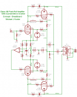
Here is my interpretation of a recent idea for SE characteristics in a PP amplifier. It's more of a SE driving PP idea but the combination of high-gm and plate feedback should allow the output stage to follow the SE driver's harmonic signature.
The driver is a sort of inverting-current-mirror which is expected to drive it's side of the push-pull output stage in anti-pentode style, where the pentode load is the plate feedback. R104, R105, R107, R108 form a bridge that feeds the inverting input of IC1 such that a signal voltage is developed on the grid of V102 that causes an opposing dynamic current in V102, opposite the signal current in V101.
Any asymmetry in the transfer function of V101 will not be cancelled, as the opposing current in V102 will cause a signal to be combined in the OPT in inverse polrity. I.e. when inverted twice, once in the current mirror and again in the OPT, the asymmetry is additive as is the signal.
So it doesn't mimic the asymmetric gm of a SE output stage driving a loudspeaker, but neither should it convert much even harmonic distortion into odd harmonic distortion given the balanced plate feedback to the current mode SE + current mirror phase inverter. The idea is to have a non-cancelling driver stage followed by a transparent power stage.
Constant balanced bias voltage for the output tubes is provided by the low pass filtered servo loop R106, C103 resulting in a constant equal current through L1, L2, and bias adjusters R113 and R114. The idea is to set the bias voltage for equal current at idle, after which adjustment would only be needed for aging or replacement of the output tubes.
Attachments
Interesting anti-triode splitter using the Op. Amp. Keeps V101 and V102 AC currents complementary and DC currents matched. The shunt regulators V103 and V104 keep screen currents out of the cathodes. The bias servoing looks like it keeps V101 and V102 DC currents matched, but it is sensitive to DC coming in the input as to what bias it balances. Are L1 and L2 coupled? I have no idea how linear the 4CX250 tubes are in class AB.
Don
Don
Last edited:
Interesting anti-triode splitter using the Op. Amp. Keeps V101 and V102 AC currents complementary and DC currents matched. The shunt regulators V103 and V104 keep screen currents out of the cathodes. The bias servoing looks like it keeps V101 and V102 DC currents matched, but it is sensitive to DC coming in the input as to what bias it balances. Are L1 and L2 coupled? I have no idea how linear the 4CX250 tubes are in class AB.
Don
Thanks for pointing out the DC issue. It made me realize there is a bigger issue in that subsonic input signals below the fc of the plate feedback will cause big problems. I think I'll use an input transformer since all my sources are balanced low-z anyway and I have some UTC A-20s or LS-30s I can use. This will allow me to simplify the power supply a little bit (unipolar input grid bias + opamp supply, ground the B+ return and supply the driver -200V) and provide an adjustment for D3A grid bias.
L1 and L2 could be coupled, but the curent plan is to use the Valab chokes I have which are separate. I'm not sure what the effect would be to voltage-couple the 2 sides.
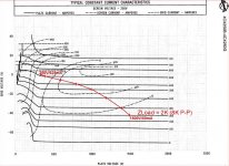
Which leads into the linearity of 4CX250s. The composite gm is about 10,000 throughout the conduction overlap between the 2 sides up to about 20,000 at peak current for this example loadline. This by itself could be a source of third harmonic distortion, but I expect the local feedback to linearize the voltage swing. The 1/gm contribution to effective Rp is therefore 50-100 ohms over the full signal swing with the feedback scheme I have. The load is 2K (8K plate-plate).
Maybe there's a 4cx250 spice model...
Attachments
Michael,
Thinking about an anti-triode splitter stage driving a class AB output stage, I believe that one wants a triode driving an anti-triode and an anti-triode driving a triode to avoid the usual distortion cancellation between stages. (I realize that your present setup is oriented toward transparancy in the output stage, this variant would be the hypothetical approach if one wanted to let the outputs distort naturally, well, at least the triode sides)
Looking at your ampl., using the Op. Amp. anti-controller scheme, one would just use cathode sense resistors for all four tubes and scale the resistors in the ratio of currents expected. Then add an Op Amp controller for each P-P side's forward link from driver tube to output tube grid. So three Op Amps total with the two added ones. V101 remains the master triode, V105 becomes an anti-triode slave to it. V102 remains anti-triode to V101, and V106 becomes a triode slave to it. Problem with this scheme though is that the driver tube plates aren't even being used, so are almost do nothings. Well, some more work needed on the idea.
Of course this all pre-supposes class A operation everywhere, so some clamps would be required to stop saturation of the Op. Amps when an output tube cuts off.
At least one feedback link makes sense so far. The V106 plate fed back to the V101 screen would be connecting triode to triode, preserving SE distortia spectra, and having the correct polarity. I am still trying to convince myself that the opposite V105 plate to V102 screen feedback would make sense distortion-wise. Alternatively, V105 plate to V101 plate may make sense since it references the master triode inversely. If so, then the dual plate to plate feedbacks in your present design would fit right in.
Anyway, just some ideas to chew on.
Don
Last edited:
Been looking at the anti-triode splitter/driver followed by class AB outputs scheme some more. Firstly, the anti-triode driver to triode output tube link doesn't need any Op. Amp. anti-controller in between. Just the usual plate to grid drive is fine there.
The triode driver to anti-triode output tube link does need something special, but just monitoring cathode currents and an Op. Amp. control is not really hacking that. The problem being that the output load impedance may not be linear or constant with frequency. So this control would need modifying to use voltages instead of currents. But then the voltage sense monitors the effects of both output tubes, not just the one to be anti'd. So I don't see a way to do this yet without big added complexity.
Then, for the crossed output plates back to driver screen feedbacks idea, it looks like both links are OK, but the result is to preserve only the driver distortion spectra (providing enough gain is in the loops, gyrator loads on the drivers). So the output of the whole thing looks like SE driver distortion, and doesn't much care whether the one output tube is anti-trioded or not. With weak loop gain though (resistor loads on drivers), the output stage distortion also chimes in some, and with no anti-triode there, will mean some of the usual odd order distortions.
A problem here, with high loop gains even (unloaded driver plates), is that the driver stage distortion also falls down toward ir-reducible constant current Mu distortion levels. This can be 50 or 60 dB (or even more) down for some tubes, and may not be hearable anymore. So seems that the ideal solution would be to get an anti-triode working on one side of the P-P output stage, and then adjust the driver resistor loads until the sought after SE effect is sufficient. This would then be a blend of the SE effect from both the driver stage and the output stage.
Don
Last edited:
A problem here, with high loop gains even (unloaded driver plates), is that the driver stage distortion also falls down toward ir-reducible constant current Mu distortion levels.
Hey Don,
I am not sure I follow your vocabulary here, but if you are refering to Michaels schematic having unloaded plates, this is not true. With the inverse feedback applied to the output tubes it will load the driver with just few kOhm (or Rnfb/(Rl*Gm+1)).
Sorry, I was referring to the hypothetical plate to driver screen feedbacks approach I mentioned earlier. Yes, agree, Michael's plate to plate feedbacks will keep the driver loaded. Seems that either approach tends to null out the output stage distortion. Just looking for some possible handle to get the output stage to look SE like also.
Don
Don
Last edited:
Why Oh why, do you have to put an op-amp in the signal path?
Sure they solve many technical problems very easily, but can't you hear what they do to the music?
I did that in my Alligator project, but the opamp and MOSFET that were used as a current source were totally out of a NFB loop. The phase splitter was alone, driving both 2-tube SE amp with own feedback by voltage, and an opamp+MOSFET CCS in another shoulder. It sounded very SEish.
"Why Oh why, do you have to put an op-amp in the signal path?"
I can't answer that for Michael, but my take on this would be that it's one way to get an "anti-triode" device for SE sound from a P-P amplifier. The Op. Amp. is being operated with minimal common mode signal on its inputs (often being the downfall of Op. Amps for distortion problems), and the AD823 or other Op. Amps like LME49860A are now in the PPM distortion range. Also, the feedback loop is quite local, just a cathode follower in it's loop. Oddly, I will next present a good reason for getting rid of it.
I just realized that the drive signal needed for making V105 an anti-triode also (besides V102) is nearly available. Just put a resistive attenuator to ground on the output of the Op. Amp., and use the attenuated tap for driving V102 and the full voltage tap/output for driving V105. Since V105 likely will require more voltage drive than the Op. Amp. can handle, one would have to resort to a tube or HV Fet differential stage to perform this function.
With V102 and V105 operating as anti-triodes, the amplifier should definately produce accurate and aligned SE effects from each stage.
Don
Why Oh why, do you have to put an op-amp in the signal path?
Sure they solve many technical problems very easily, but can't you hear what they do to the music?
Regards, Allen (Vacuum State)
And I thought you were going to say why, oh why do I need so much power

But seriously, I have been thinking about replacing the mirror side D3A with a FET or FET cascode and a common CCS tail to get my anti-triode behaviour and going with the constant voltage gyrators I used in the 4-65A project instead of the chokes. That will take driver tube current out of the output bias equation, and provide a place to insert a HPF in the response which is above the RC plate feedback HPF to solve the subsonic peak problem.
Another advantage is this circuit is AB2-capable with a higher voltage on Q1 and Q4.
Cheers,
Michael
Attachments
(...)
I just realized that the drive signal needed for making V105 an anti-triode also (besides V102) is nearly available. Just put a resistive attenuator to ground on the output of the Op. Amp., and use the attenuated tap for driving V102 and the full voltage tap/output for driving V105. Since V105 likely will require more voltage drive than the Op. Amp. can handle, one would have to resort to a tube or HV Fet differential stage to perform this function.
With V102 and V105 operating as anti-triodes, the amplifier should definately produce accurate and aligned SE effects from each stage.
Don
Posts crossed!
Now there's a FET differential stage, but I'm not sure I follow the coupling idea. Currently the new circuit uses plate feedback to get the V106 anode signal to balance the anti V/I converter (Q3). Isn't it V106 I want to be the anti-triode so there is a triode half cycle (V105) and an anti-triode half cycle (assuming sine wave conditions for the moment)?
Michael
Michael,
"Isn't it V106 I want to be the anti-triode so there is a triode half cycle (V105) and an anti-triode half cycle "
Think of two triode tubes in cascade. The distortion of the driver is sometimes intentionally made large, so as to cancel distortion from the output tube. This only works for even harmonics though, just like P-P. Since the two tube currents are out of phase with an inverting driver, the characteristic curves are relatively inverted.
Now the anti-triode has the SAME distortion curvature as a triode when its current is inverted, so cascading an anti-triode after a triode driver matches the distortion curves. No cancellation then. Same thing for a triode after an anti-triode.
I'm not seeing any obvious way to anti-couple the latest version, but then it took me a few days to see how to do the other version. I was amazed that it could be done at all. It is somewhat approximate, since V102 and V105 were not matched devices earlier (or even operating in the same class mode), but probably close enough.
Don
Last edited:
I am very much interested in this topology. I tried to shape same effectAny asymmetry in the transfer function of V101 will not be cancelled,
circuitry without semi-conductor. As the result, I figured out the attached
circuitry to use center tapped transformer. Since a lack of SPICE model
of existing transformer in TINA simulator, I am using ideal transformer model
with center-tapped one.
The following lists modifications from the Koster's original.
*Signal Inverting: transformer
*D3a > C3g
*4CX250B > EL34
*P-G feed back: 100% > reduced by resistors divided
Although the shown schematic is not fine tuned in distortion,
the component of 2nd harmonics is bigger than conventional PP amp.
Damping Factor is about 1.6 (@8ohm, 1W).
Anyway, Koster's idea has big potential to get good sonic.
Attachments
Why not use DC-coupling of the inverse feedback resistor if you are worried about subsonics? Then you can let the currents add: 10mA from the feedback-path and and 10mA from the choke-path. 15W over the feedback resistor though
There will be 5W dissipated in Rfb at full signal as it is ;-) For 2500V P-P across the Rfb I will use 4x 39K/3W/1000V resistors in series. The DC conection would need 10W resistors but maybe could increase the resistance and decrease the driver current swing somewhat.
Cheers,
Michael
Michael,
"Isn't it V106 I want to be the anti-triode so there is a triode half cycle (V105) and an anti-triode half cycle "
Think of two triode tubes in cascade. The distortion of the driver is sometimes intentionally made large, so as to cancel distortion from the output tube. This only works for even harmonics though, just like P-P. Since the two tube currents are out of phase with an inverting driver, the characteristic curves are relatively inverted.
Now the anti-triode has the SAME distortion curvature as a triode when its current is inverted, so cascading an anti-triode after a triode driver matches the distortion curves. No cancellation then. Same thing for a triode after an anti-triode.
I'm not seeing any obvious way to anti-couple the latest version, but then it took me a few days to see how to do the other version. I was amazed that it could be done at all. It is somewhat approximate, since V102 and V105 were not matched devices earlier (or even operating in the same class mode), but probably close enough.
Don
Thanks for that explanation. Now I think I follow your reasoning. Instead of the triode-antitriode in an opposing configuration as we have been showing up till now, you propose the triode-antitriode in cascade configuration. The practical implications still escape me though. Some kind of crossed connection... The output tubes will still have their class AB tetrode composite gm curve?
Michael
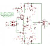
I am very much interested in this topology. I tried to shape same effect
circuitry without semi-conductor. As the result, I figured out the attached
circuitry to use center tapped transformer. Since a lack of SPICE model
of existing transformer in TINA simulator, I am using ideal transformer model
with center-tapped one.
The following lists modifications from the Koster's original.
*Signal Inverting: transformer
*D3a > C3g
*4CX250B > EL34
*P-G feed back: 100% > reduced by resistors divided
Although the shown schematic is not fine tuned in distortion,
the component of 2nd harmonics is bigger than conventional PP amp.
Damping Factor is about 1.6 (@8ohm, 1W).
Anyway, Koster's idea has big potential to get good sonic.
Thanks!
Your coil based inverter/splitter is a very interesting approach!
Some other differences I see:
* Class A vs class AB
* Inverter has equal and opposing nonlinear gm between the C3G tubes. The nonlinear gm of V6 should cancel the nonlinear gm of V5, i.e. won't the f2 distortion in the input stage cancel?
Also found something in common with my latest circuit. The drive voltage between P-P sides will be asymmetric. The cathode Ri of V6 (1/gm) forms a voltage divider with R1 and reduces the drive voltage to V5 relative to the drive voltage on V6. My circuit has a similar issue. One way to balance the AC voltage is reduce the value of the cathode (source) resistor on the slave side. The plate feedback coupling side to side through the OPT may cancel some of the imbalance. But your f2 second harmonic distortion may be a result of this AC imbalance.
Cheers,
Michael
Last edited:
Re: Michael,
"Instead of the triode-antitriode in an opposing configuration as we have been showing up till now, you propose the triode-antitriode in cascade configuration. The practical implications still escape me though. "
I just meant that whenever the signal gets inverted, there should be a corresponding T to anti-T or anti-T to T transformation. So with P-P drivers to P-P outputs, the diagonal tubes would ideally be anti-Ts.
Class AB though, complicates this considerably, since a triode output tube would be traversing its entire curve while only powering 50% of the cycle. If the opposite output tube were successfully anti-T'd, then it would be traversing the full triode curve in 50% of the cycle too. This would duplicate the triode response twice in a full cycle, likely causing high harmonic distortion at the crossover. So some way would be needed to get each output tube to use 50% (and opposite 50%s at that) of the triode curve.
Transparency of the class AB outputs is certainly the most straightforward approach to solve this.
Don
- Status
- This old topic is closed. If you want to reopen this topic, contact a moderator using the "Report Post" button.
- Home
- Amplifiers
- Tubes / Valves
- PPAB with plate feedback, current-mirror driver