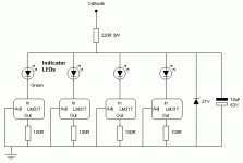
I have a simple LM317 CCS circuit in the cathodes of my output tubes - it seems to work well, apart from a millivolt level oscillation problem I discovered on my scope. Attached is the circuit. It seems to be oscillating into the Mhz region, I can't remember which scale I had the scope on, but it was near the limits of my 20Mhz bandwidth. The amplitude of the oscillation is about 20mV.
Each LM317 is programmed for 12.5mA, which may actually be too low. My decoupling capacitor is a 1uF electrolytic (not 10uF like in the schematic, sorry about that), which may be the problem too.
Perhaps the problem could be solved with a smaller ceramic type decoupling capacitor?
I have attached the circuit
Attachments
Hi,
That's because you can't really use 317's like that. They need voltage across them to work properly.
I suggest a "real" CCS, unless you want to toss in a -V supply to make the 317's work right.
Cheers!
**afterthought**
Try losing the LED's. Maybe an extra 1.7V will "give them a kick"
That's because you can't really use 317's like that. They need voltage across them to work properly.
I suggest a "real" CCS, unless you want to toss in a -V supply to make the 317's work right.
Cheers!
**afterthought**
Try losing the LED's. Maybe an extra 1.7V will "give them a kick"
Last edited:
Hi,
That's because you can't really use 317's like that. They need voltage across them to work properly.
I suggest a "real" CCS, unless you want to toss in a -V supply to make the 317's work right.
Cheers!
**afterthought**
Try losing the LED's. Maybe an extra 1.7V will "give them a kick"
Oh well they do have about 7V across them - the 220R resistor is just there to drop some of the voltage. Surely an LM317 is OK with drawing 12.5mA over 7V?
why not just look to SY's "Red Light" amp -- and by the way, an LM317 has impedance and phase.
Most likely, but it's only having to sink DC - it is bypassed by a 470uF capacitor. It is your standard cathode bias circuit, but with a CCS
Sounds as if there might be a bit of radio pickup since you are an excellent radio antenna and you increase the oscillation. Try replacing the LED's with 10R resistors right on the pins.
Despite what people will say they work brilliantly with almost no sonic signiture.
Shoog
Despite what people will say they work brilliantly with almost no sonic signiture.
Shoog
I was just thinking about your circuit.
I don't understand why you have four LM317's when each is only carrying 12.5mA. I have used the LM317 and had it reliably working at 30V and 100mA for well over a year. If its adequately heatsinked then I cannot see why one LM317 will not suffice.
Shoog
I don't understand why you have four LM317's when each is only carrying 12.5mA. I have used the LM317 and had it reliably working at 30V and 100mA for well over a year. If its adequately heatsinked then I cannot see why one LM317 will not suffice.
Shoog
I was just thinking about your circuit.
I don't understand why you have four LM317's when each is only carrying 12.5mA. I have used the LM317 and had it reliably working at 30V and 100mA for well over a year. If its adequately heatsinked then I cannot see why one LM317 will not suffice.
Shoog
It is retrofitted into an amp where fitting a heatsink would be a problem and fitting a heatsink would be a bit of a pain - but luckily with four of them they only get slightly warm to the touch without a heatsink
You have to expect some noise, both from LEDs, zeners, and the LM317.
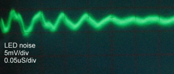
I observed a little noise from my LED referenced CCS. Zooming in on the scope I got this image. Seems similart to what is described here.
You can modulate any diode, certainly a clear one, with light from a fluorescent --- but the period is too short for this to be the case.
You can also get some ringing from the interaction of the rectifier diodes and transformer leakage inductance -- if it's frequency is high enough it will transmit just like a short-wave signal.
Maybe a decade ago when I was using "Simple Switchers" from National I asked the tech guy if I could just mount one atop another since the circuit drew a bit more than I had thought -- like Anatech's wife says "Just because you can, doesn't mean you should..."
Bolt one LM317 to the floor of the chassis using thermal grease and an insulator.
Last edited:
Bolt one LM317 to the floor of the chassis using thermal grease and an insulator.
I don't want to drill it, it's a Radford STA-15 chassis
Clipping a 100nF capacitor from the output pin to ground seems to cure it! I guess the LM317 likes to see a slightly capacitive load, and the data sheet does warn of a small range of capacitances where they become unstable. The suggestion is to load it with a small capacitor to swamp this! Other datasheets say that the LM317 is stable with no output capacitor 
Why four LM317s at 12.5ma driving a common tie point to a single cathode? Trying to avoid using a heat sink?
Just get rid of three LM317s along with the associated resistors and LEDs, and decrease the 100R to 25R and use an appropriate heat sink. Eliminate the Zener, and 220R unless you are trying to intentionally provide nfb with a cathode resistor.
I'd also recomend a larger decoupling cap for low end response, but 1uF should be ok.
What tube is this driving? 12BQ5, 12AQ5, ??
The Zener is to provent too much voltage across the LM317s should the cathode voltage drift too high, it is not normally in conduction. The whole thing is bypassed by a 470uF electrolytic (the actual valves are EL34s). The reason for 4 LM317s is to avoid the need for heat sinks, because unfortunately they would be too tall for the chassis
You mentioned that you don't have room for a heat sink and aren't real happy about drilling holes in the chassis. Surely, there must be other screws that go through the chassis. Could you use one of those?
Actually, there are heat sinks that are made for clipping onto a TO-220 package (such as the LM317). They're not very big but provide a fair amount of cooling for their size. Maybe one of those would fit. You can find examples of this on www.digikey.com (and others) by searching for TO-220 heatsink.
~Tom
Just make your own heatsink - take two pieces of metal (preferrably black electroplated aluminium) sheet as large as you can fit inside your enclosure without actually touching any other metallic part, screw them onto the tab of LM317 (one on each side - you'll have to cut a small portion away for the front part) and bend them outwards so they form an 'X' when viewed from the top in order to improve the airflow around them.
If 4 tabs can dissipate all the heat generated, it should take much in the way of heatsink to accomplish the same.
If 4 tabs can dissipate all the heat generated, it should take much in the way of heatsink to accomplish the same.
Dids you use high-efficiency LED's ?
They may cause the oscillation-problem , because they have some regulator circuitry inside that make some HF-switching-noise.
LM317 should perform well without the output biassing capacitor on a reactive load. The capacitor is only nescessary with an inductive load.
biassing of the tube needs a negative voltage on the grid , in case of automatic bias that means you want a positive voltage on the cathode by a cathode resistor. So why the hell did you use a CCS ? You need a constant voltage device !
- Status
- This old topic is closed. If you want to reopen this topic, contact a moderator using the "Report Post" button.
- Home
- Amplifiers
- Tubes / Valves
- LM317 oscillating in cathode circuit

