Hello,
I need some advice from the tube gurus here.
I want to build a high power amp. I have a 100watt 4.5k vintage transformer I want to put to good use. I have narrowed down my search to two amplifiers:
http://www.plitron.com/vtvkt88.asp
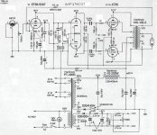
http://www.tube-amps.net/images/KT88_PP_01/KT88_Schematic.jpg
Which is a better designed amp? As in more stable (against oscillation) and rugged (can be pushed to its limits without burning up)?
Which tube can take more abuse the KT88 or 6550?
Let me know what you guys think of the designs?
Thanks
I need some advice from the tube gurus here.
I want to build a high power amp. I have a 100watt 4.5k vintage transformer I want to put to good use. I have narrowed down my search to two amplifiers:
http://www.plitron.com/vtvkt88.asp
http://www.tube-amps.net/images/KT88_PP_01/KT88_Schematic.jpg
Which is a better designed amp? As in more stable (against oscillation) and rugged (can be pushed to its limits without burning up)?
Which tube can take more abuse the KT88 or 6550?
Let me know what you guys think of the designs?
Thanks
I think 525V on the screens of ultralinear output tubes is excessive, even for KT88s/6550s. This is a problem with both. Reducing that to 450V would be a "safe" solution.
The first amp is a Williamson, so it may be prone to low frequency instability unless you make a few provisions with the coupling caps (I'd stagger the poles further than they are, by using .47uF for the first set and .1uF for the second set). Depending on the output transformer, it may also have high frequency stability issues, so you'd want a good scope and generator to work out proper compensation. The Williamson requires a VERY good output transformer, so if yours isn't known to have 10Hz-100kHz bandwidth and good high frequency behavior, I would hesitate to go this route.
The second amp is a Mullard design, and will be easier to stabilize. However, it will have more gain and noise than the Willy. Again, it will still require some feedback compensation if you want to do it right - so be prepared to get out a scope and generator.
I am pretty sure that the Morgan Jones 3rd edition book has good descriptions of both circuits, and probably some hints.
Jon made what IMO is the crucial point. Williamson topology is vulnerable to instability. Go with the Mullard style circuitry.
As for getting the gain right, use a different small signal tube complement. The 12AT7 is head and shoulders above the 12AX7, in LTP service. Depending on drive signal level, choose a high gm linear triode as the voltage amplifier. Candidates (in order of increasing μ) include the 6FQ7, 12AV7, and 6GK5.
BTW, use a 10M45S CCS instead of a resistor in the tail of the LTP.
Anyone know why the second schematic has just one diode in the HT power supply? Where diodes expensive back when this was drawn or is there a good reason to use a 1/2 wave rectifier?
I've seen this more than once in older schematics. A newer design would have a full wave design and with this HT voltage, use two diodes in series.
I've seen this more than once in older schematics. A newer design would have a full wave design and with this HT voltage, use two diodes in series.
Anyone know why the second schematic has just one diode in the HT power supply? Where diodes expensive back when this was drawn or is there a good reason to use a 1/2 wave rectifier?
The schematic is drawn wrong. There should be a bridge rectifier instead.
The schematic is drawn wrong. There should be a bridge rectifier instead.
But I've seen many example of this in schematics of this era. Another example is the "Classic" Fender 6G15 reverb unit. (the device that gives 60's surf music its unique sound) The 6G15 drawing can't be in error because you can see on the second page the physical layout matches the schematic and the units were actually built that way if you happen to peek inside. Fender now builds re-issues with a four diode bridge and a 6v6 replacing the 6k6 but otherwise identical. There must have been good reason for the old design. There are other examples but with this I can be 100% certain it's not a drawing error.
http://www.schematicheaven.com/fenderamps/reverb_6g15_schem.pdf
Yes today we'd build it different. Just trying to understand the history. (That, and I'm actually building a copy of the 6G15.)
I agree with the others about the instability of the Williamson.
I also agree that, in your second schematic, a 12AT7 would be a better tube to use than a 12AX7, although I don't see a 12AX7 in your schematic. I think Eli must have meant instead of the 12AU7? Trouble is, that will give a lot more gain, so a 6FQ7/6CG7 would be a better choice. You certainly should replace the 12AU7, which is not good tube to use here because of its non-linearity. As Eli says, use a CCS in the tail. If gain is too high, try removing the EF86 cathode bypass cap.
The 0.68uF EF86 screen bypass cap should be connected between screen and cathode, not screen and ground. The way it's shown in the schematic will cause positive FB.
Using a single diode to rectify HT makes no sense IMHO, whether it was meant to be drawn like that or not. Use a bridge rectifier.
The 6550s/KT88s should have screen stoppers/droppers of about 1k when used like this.
You could encounter problems setting the OP tubes' bias because, although there is a balance adjustment, there is no overall bias voltage adjustment.
Last edited:
The Williamson as drawn has NO power switch on the PS???????. There is no bleeders for the bias supply.......could be a safety issue, but I would bleed it SOME!
There is also no warm-up protocol, full B+ on turn-on, wouldn't have a chance to warm-up. Not good for longevity...short term perhaps.
Note the fuse at B+...it was added later after the schematic was drawn up.
__________________________________________-Rick....
There is also no warm-up protocol, full B+ on turn-on, wouldn't have a chance to warm-up. Not good for longevity...short term perhaps.
Note the fuse at B+...it was added later after the schematic was drawn up.
__________________________________________-Rick....
- Status
- This old topic is closed. If you want to reopen this topic, contact a moderator using the "Report Post" button.
- Home
- Amplifiers
- Tubes / Valves
- Help me choose between two designs