Too bad they don't ship to Canada.
Hey guys, has anyone tried a mosfet buffer in the 26 preamp? I get lower thd in simulation. I might just try it one of these days.
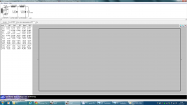
The second image is the thd values for the one with the buffer, the third image for the circuits without a buffer. I guess this could be the poor man's alternative to an output transformer when the next stage has a lowish input impedance.
Hi Relu,
I did it on a breadboard - we discussed here long time ago - and liked the sound compared to simple CCS. DHTRob build it as well and was very pleased.
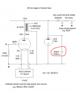
Here is my latest idea for 01a, I'd probably replace the MOSFET gyrator for a BJT/hybrid cascode to improve the performance at low currents. Anyway, using the output cathode follower filaments as filament bias resistor is a great choice for a poor man's preamp!
Cheers
Ale
http://www.bartola.co.uk/valves/2013/01/19/01a-preamp-revisited-2013/
Ale, I've been running the gyrator for quite a long time. Not a complex one like you have with two devices and a CCS in the gyrator bias because I saw that I can have good enough performance with just one device as in the schematic above.
As for the mosfet buffer, I was tempted to try it out tonight but I'd need to beef up the supply. I also don't need lower output impedance either, so... I'll just leave it as it for now.
Felipe, such a buffer could power your 300 ohm headphones.")
As for the mosfet buffer, I was tempted to try it out tonight but I'd need to beef up the supply. I also don't need lower output impedance either, so... I'll just leave it as it for now.
Felipe, such a buffer could power your 300 ohm headphones.
It looks really good, congratulations...now on to the next project !
Thanks James!
Abe
Iko wrote exactly what I was going to write - here's the schematic. I don't know if you need a grid stopper.
Arrived the two VR150, Andy the paralleled cap value can be other value? If I want two VR150 + CCS it's enough to set the DN2540 current in each CCS to 10mA?
TIA
Felipe
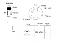
You only need one 0D3 - don't get complicated and put in unnecessary components. The 0D3 supplies the two 26. So if they are 5mA each, that's 10mA. You then have to add the current for the 0D3 which is 22.5mA, so your total is 32.5mA. You set the DN2540 for that. Start out with the trimmer set to 40 ohms. You adjust the trimmer using ohms law for the dropper resister before it, so have your multimeter across this resistor while you adjust. For a 100R resistor and a current of 32.5mA you get a voltage drop of 3.25v. You could use a larger dropper resistor, so for 1K it would be 32.5v. You can mount the DN2540 directly to the underside of the chassis top plate. For the trimmer, join the two legs under the trimmer adjust screw, and these go to the 1K resistor. The third leg goes to pin 3 of the DN2540. Keep these components right on the pins of the DN2540. For the 0D3, wire it as shown. There's an internal jumper from pin 3 to 7, so the tube only works when it's inserted. That's a safety measure. Capacitors on either side of the dropper resistor should be polypropylene - 40uF is good but use what you can, starting from 10uF. For the small capacitor in parallel with the 0D3 you can use a Russian 0.056uF teflon, or a polystyrene or polypropylene. The value must not be greater then 1uF.
Attachments
Last edited:
just small addendum - neon stabilizers are having few pins shorted with one important function - circuit wiring need to be made in that fashion that upstream side is connected to one of shorted pins , while downstream side is connected to other shorted pin
having that , when tube is pulled from circ ( accidentally or not ) , voltage is Dodo , so loading side can't be killed
having that , when tube is pulled from circ ( accidentally or not ) , voltage is Dodo , so loading side can't be killed

Hi Stajo - as you show, 3 and 7 are internally joined. So on the socket you join 3 (or 7) to 5 (anode). Then use 7 (or 3) for the other connection. Does it actually matter if 7 or 3+5 is the input or the output?
No
Just inversed B+ in/out Andy posted?
I have FT-3 15nF or 100nF, wich one? or I can parallel two 15nF to have 30nF or parallel 3 15nF to have 45nF?
What's the max, input voltage for VR150?
What's the max, input voltage for VR150?
I'm sure there is one but you will be fine. Its more the current 5-40 mA you should watch out for. You need some 30-40 V more Vin then Vout to make it lit.
I'm sure there is one but you will be fine. Its more the current 5-40 mA you should watch out for. You need some 30-40 V more Vin then Vout to make it lit.
Canc check the current with a DVM in series with the DN2540? Attached pic with PSU used I believe is OK?
Attachments
You can mount the DN2540 directly to the underside of the chassis top plate.
Felipe, if you do like this, please be very careful with insulation. Use a thick aluoxide and rather clamps then thru hole screw. HV should have at least a mm or 2 to touchabe things, even if its grounded to earthground.
- Home
- Amplifiers
- Tubes / Valves
- #26 pre amp