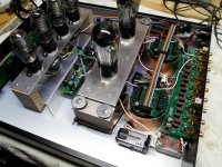
I'm happy enough with the bias battery under the input transformer that I've permanently changed the preamp, removing the input capacitors and grid bias resistors, and relocating the batteries to where the input caps were previously.
It sounds much better this way, and the signal path is a little bit neater as well. Pic below.
It sounds much better this way, and the signal path is a little bit neater as well. Pic below.
Attachments
Hello, just a question to Magz.
I have a 26 preamp with input capacitors and battery bias and just so happen to have two LL1676 input transformers laying around. I probably need to have them wired in 1:1 but how do you calculate the RC network and what is the purpose of the battery bypass?
Very nice work on your preamp by the way...
Hello, just a question to Magz.
I have a 26 preamp with input capacitors and battery bias and just so happen to have two LL1676 input transformers laying around. I probably need to have them wired in 1:1 but how do you calculate the RC network and what is the purpose of the battery bypass?
Very nice work on your preamp by the way...
Mine are wired 2:1 parallel/parallel and that is perfect for use with the autoformer outputs/volume controls. How you wire them determines the RC network you need, so parallel/parallel, parallel/serial, serial/parallel and serial/serial all have somewhat different resonances and require somewhat different networks. I used a function generator and oscilloscope to determine what gave the best square wave performance; the easiest method is to wire the cap to a pot and vary the pot to get the best setting, then replace the pot with a resistor. I split the resistor value in two and used an RCR setup to isolate the transformer somewhat from the cap.
I put in a small bypass on the battery (.01uf polystyrene) in case there is any HF noise that needs to be bypassed to ground and may be stopped by the battery.
I thought that it was not recommended to use the secondaries in parallel on the LL1676 ("frequency abberations" according to KevinC) but I'll guess it depends on the expertise of the user.
I have no scope but perhaps you can recommend some starter values on the RC network just to try? Or maybe it's best to use nothing just to hear if the transformer has any potential of bettering my Duelund Cast?
I have no scope but perhaps you can recommend some starter values on the RC network just to try? Or maybe it's best to use nothing just to hear if the transformer has any potential of bettering my Duelund Cast?
I thought that it was not recommended to use the secondaries in parallel on the LL1676 ("frequency abberations" according to KevinC) but I'll guess it depends on the expertise of the user.
I have no scope but perhaps you can recommend some starter values on the RC network just to try? Or maybe it's best to use nothing just to hear if the transformer has any potential of bettering my Duelund Cast?
I know of Kevin's thoughts, but my scope showed the 2:1 (parallel) actually had less HF ringing than 4:2 (serial) for a 2:1 connection. I was using a CAST 0.22, but in addition to the LL1676; the transformer alone is definitely better.
I'll tell you what..I have a spare LL1676. Tell me how you want to hook it up, and I'll scope it and recommend an RC.
Vbenonisen,
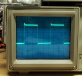
I had some time this morning, so I wired up the LL1676 in 1:1 as 1+1:2||2. The RC network that worked well was 2nF and 2Kohm.
2K square wave scope shots below: first is the LL1676 with no RC, second is with 2nF+2Kohm.
I had some time this morning, so I wired up the LL1676 in 1:1 as 1+1:2||2. The RC network that worked well was 2nF and 2Kohm.
2K square wave scope shots below: first is the LL1676 with no RC, second is with 2nF+2Kohm.
Attachments

In any case, the transformer wouldn't be damaged by the DC, the core would saturate, which can be remedied by passing an AC signal at the saturation level...demagnetizing, in other words.
Thank you for the feedback Magz. I'll give it a shot.
Cheers,
Rich
I just found an interesting web site on impedance testing of different kinds of power supplies:
Testing Power Supplies
It doesn't seem to be a problem shunting VR tubes with bigger capacitors as long as it is a correctly sized resistor in series with the capacitor. Haven't tried it yet but I'll guess I have to give my share to science and give it a go (any warnings are very welcome).
Testing Power Supplies
It doesn't seem to be a problem shunting VR tubes with bigger capacitors as long as it is a correctly sized resistor in series with the capacitor. Haven't tried it yet but I'll guess I have to give my share to science and give it a go (any warnings are very welcome).
Last edited:
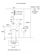
Hello again. I'd like to raise the issue of the anode load for the 26. I've been using 2x Hammond 156C chokes in series, but this is prone to hum. As an alternative I'm going to try and optimise a Lundahl LL1667/10mA. In it's raw state this doesn't sound as good as the Hammond combination, but it should have less hum. I tried adding a 4.7k resistor between the Lundahl and the anode and this seemed to clean up the sound. The Lundahl datasheet lists 270H inductance for the 15mA version, so I'm thinking the 10mA version should be over 300H. That's the same as the Hammond combination. Nevertheless, adding a resistor seemed to help.
Can anyone comment on this? Am I correct in adding the resistor between anode choke and anode, not anode choke and B+? Any comments about the size of the resistor? Has anybody played around with choke+resistor combinations?
Can anyone comment on this? Am I correct in adding the resistor between anode choke and anode, not anode choke and B+? Any comments about the size of the resistor? Has anybody played around with choke+resistor combinations?
Hi Andy,
Hope you had a great Christmas!
Adding a resistor between the primary and the anode will increase the effective anode resistance and therefore impacts the low frequency response. The reduction of the hum you perceive is in essence a degradation of the bass response...
Ale
Hope you had a great Christmas!
Adding a resistor between the primary and the anode will increase the effective anode resistance and therefore impacts the low frequency response. The reduction of the hum you perceive is in essence a degradation of the bass response...
Ale
Hello Ale! I see you are in Saturday Morning Hi-Fi mode..... thanks for coming in here.
I think we can't rule out the physical construction of the choke as a source of hum - the Hammonds seem to pick up hum more than the Lundahls. Maybe there is more than one factor in play here? Have you tried a choke+resistor combination any time?
I think we can't rule out the physical construction of the choke as a source of hum - the Hammonds seem to pick up hum more than the Lundahls. Maybe there is more than one factor in play here? Have you tried a choke+resistor combination any time?
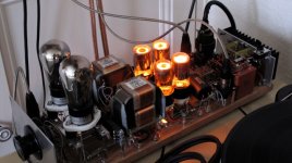
I'm certainly working this morning. I've been building DHT power supplies for the last three days (4-65a and 46 in filament bias) 
I haven't tried that combination am afraid. The LL2745 I'm currently using in the 26 preamp are very quiet. They are not shielded in my case as I'm still running with the breadboard (see picture attached). Of course if you place your hand very close to the OT you will notice the induced hum. Otherwise is not noticeable. If you want to use the chokes then I will suggest to place them inside their own little metal boxes?
From a sound point of view, would be interesting to hear your feedback as to whether the addition of the resistor will improve sound rather than reducing hum (and therefore also impacting the bass response of the pre-amp)...
Ale
Attachments
Last edited:
Hi!
putting a resistor in series with the choke will not impact the frequency response. In fact it would even improve it. A few kOhms should not make a big difference though. I have found placement of anode chokes to be critical. Also be careful how you orient the two chokes of each channel. They can interact with each other and produce warps in the frequency response.
Thomas
Hi!
I'm sure its not the transformer that picks up the hum, but probably the 26s which are prone to pick up of external fields. I have used these transformers in phonostages and they don't pick up anything. That's with signals at least 20dB below line level
Thomas
Of course if you place your hand very close to the OT you will notice the induced hum.
I'm sure its not the transformer that picks up the hum, but probably the 26s which are prone to pick up of external fields. I have used these transformers in phonostages and they don't pick up anything. That's with signals at least 20dB below line level
Thomas
Hi!
putting a resistor in series with the choke will not impact the frequency response. In fact it would even improve it. A few kOhms should not make a big difference though. I have found placement of anode chokes to be critical. Also be careful how you orient the two chokes of each channel. They can interact with each other and produce warps in the frequency response.
Thomas
Thomas,
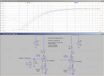
Technically, I think it does. Albeit it will only be a minor impact and as you say it may be unnoticed or perhaps add some good results. If we don't take into account the load, then the pole is impacted as you have the inductor in series with the added resistance. I did a quick simulation to show this.
Ale
Attachments
You may be right here as both are very close. When I tested that I found that the hum increased with the hand close to the 26 as expected, but then moving it over the transformer it had same effect. Can't contradict what you're saying as in my case both are very close.Hi!
I'm sure its not the transformer that picks up the hum, but probably the 26s which are prone to pick up of external fields. I have used these transformers in phonostages and they don't pick up anything. That's with signals at least 20dB below line level
Thomas
Ale
- Home
- Amplifiers
- Tubes / Valves
- #26 pre amp