I don't use the 26 anymore, but when I did I used two Hammond 156C chokes in series, bolted top to bottom and wired out of phase - all the details are in the thread somewhere. That was a good sound and cheap to achieve. This gives you all the gain of the 26 with a Russian teflon cap in my case. The issue with this setup is hum - the Hammonds are prone to hum pickup so you need to place magnetic components carefully, and well away from the chokes.
Exactly, I did build an 71A preampli with anode choke of 150H. Hum is a bit quite although I isolate power transformer in separate chassis. The preampli lies next to the power ampli, so I don't have any problem on impedance matching. high and midrange of this are fantastic.
I have an idea. Take 27/56/76 or 6J5/ 6SN7 is role of CCS for 26, likes SRPP circuit. That means these tubes are top half, and 26 is bottom half. I will experiment that in near future. That time the schema will be simplest.....
")
Last edited:
I have an idea. Take 27/56/76 or 6J5/ 6SN7 is role of CCS for 26, likes SRPP circuit. That means these tubes are top half, and 26 is bottom half. I will experiment that in near future. That time the schema will be simple.....
Top half tube is maybe a DHT, I can take 2 windings of filament in out of phase. So no need to get DC filament because AC hum from filament will be a lot canceled together.
... promissing
The "cancelling" of ac in filaments is what a hum-pot tries to do.... it's not good enough for a line amp, firstly because the filament is not perfectly symmetrical, - and secondly because the cathode generates second-harmonics of the filament current.
The sound is much worse as well, because the ac-current generates cross-products with the music (intermodulation).
The sound is much worse as well, because the ac-current generates cross-products with the music (intermodulation).
I had a lovely 71a loaded with Mu follower gyrator. Filaments DC using Rod's regulator and was dead quietExactly, I did build an 71A preampli with anode choke of 150H. Hum is a bit quite although I isolate power transformer in separate chassis.
Go for dc filaments!
Ale
What happened with 4P1L on epay? Only 2 sellers left...
One from Ukraine (selling matched pairs) and one from Czech Republc...
Hi Anatoliy,
Too late, all sold out thanks to us preaching all along the beauties of this valve. I bought about 15,000
Ale
OK, here are some pics of my completed 26 linestage. First the whole package of PS, linestage, umbilical and remote, then a closeup of the linestage, then the linestage in operation on my workbench.
Attachments
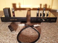
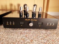
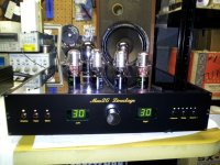
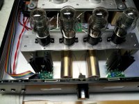
OK, here are some pics of my completed 26 linestage. First the whole package of PS, linestage, umbilical and remote, then a closeup of the linestage, then the linestage in operation on my workbench.
Hi Magz,
Superb job, well done! Very neat! I wish mine could look like that.
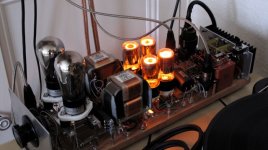
Here is my current 26 preamp incarnation with LL2745 and HT using russian glow tubes and dn2540 CCS "a la Gary Pimm"....
Ale
Attachments
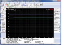
Now some Frequency Response Plots.
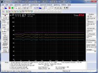
First is pink noise, at 0dB, -6dB, -12dB and -18dB attenuation at 1/24th octave resolution.
Second shows the impact of the lossy parafeed cap + resistor on the frequency response at -18dB. The plot with the 10dB hump at ~13Hz is using only a 1uF parafeed cap, while the flat plot also has a 3.3uF + 8,080ohm resistor in series added to the parafeed cap. The lossy parafeed (also known as DrP or damped resonance parafeed) really flattens out the hump and extends the FR much lower - my sims say 4.8Hz for the -3dB point.
Attachments

Last edited:
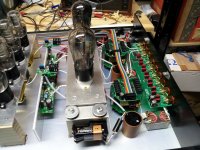
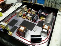
So the B+ power supply is Hammond 374AXP - 5R4GY - LCLC followed by (for each channel) a 10uF cap - cascoded CCS + VR150-VR75 - cascoded CCS - 26 tube.
Filament supply (for each channel) is Hammond 10V 50VA split bobbin transformer - schottky bridge - 6mH, 2A Hammond choke - 33,000uF THSA Cap - Bybee Music Rail - 1000uF cap - Coleman regulator. Set at 1.5V.
The other small transformer at the front of the PS is a 10V 20VA Hammond for the control circuit power supply 9VDC.
Signal path is input - LL1676 transformer wired 2:1 (both sides in parallel) - 0.22uF Duelund CAST cap - 26 tube - 1uF Duelund CAST cap with 3.3uF Mundorf Supreme and 8080ohm TX2575 resistor in parallel - Bent Audio TAP autoformer volume control (~150H) - output.
Magz 
some still at ebay.de .... (but not for long I think) quite pricey though ..
4P1L | eBay
What happened with 4P1L on epay? Only 2 sellers left...
One from Ukraine (selling matched pairs) and one from Czech Republc...
some still at ebay.de .... (but not for long I think
) quite pricey though ..4P1L | eBay
So the B+ power supply is Hammond 374AXP - 5R4GY - LCLC followed by (for each channel) a 10uF cap - cascoded CCS + VR150-VR75 - cascoded CCS - 26 tube.
Filament supply (for each channel) is Hammond 10V 50VA split bobbin transformer - schottky bridge - 6mH, 2A Hammond choke - 33,000uF THSA Cap - Bybee Music Rail - 1000uF cap - Coleman regulator. Set at 1.5V.
The other small transformer at the front of the PS is a 10V 20VA Hammond for the control circuit power supply 9VDC.
Signal path is input - LL1676 transformer wired 2:1 (both sides in parallel) - 0.22uF Duelund CAST cap - 26 tube - 1uF Duelund CAST cap with 3.3uF Mundorf Supreme and 8080ohm TX2575 resistor in parallel - Bent Audio TAP autoformer volume control (~150H) - output.
Oooops. Forgot a stage in the Filament supply. It's
Filament supply (for each channel) is Hammond 10V 50VA split bobbin transformer - schottky bridge - 2.2uF 10W resistor - 680uF cap - 6mH, 2A Hammond choke - 33,000uF THSA Cap - Bybee Music Rail - 1000uF cap - Coleman regulator.
Based on Rod's design, with a few minor deviations.
More details.
The filament transformers and HT transformer are all snubbed with .022uF caps and 330ohm resistors, the HT from each side of the secondary to center tap and the filaments across the secondary.
Power switch is wired so that the HT cannot be applied unless the Filament is on.
The filament transformers and HT transformer are all snubbed with .022uF caps and 330ohm resistors, the HT from each side of the secondary to center tap and the filaments across the secondary.
Power switch is wired so that the HT cannot be applied unless the Filament is on.
I had a lovely 71a loaded with Mu follower gyrator. Filaments DC using Rod's regulator and was dead quiet
Go for dc filaments!
Ale
DC filament (CLC circuit, C totally 10000 uf, L 200mH) is used for 71A, with good filtered negative supply for fixed bias. I guess hum from my plate choke. I did place 2 HT chokes and 2 filment chokes a little bit near anode choke and B+. next step is isolating all that choke in separate chassis.
Op point of 71A is 130-150V/ 10-11mA. I feel the sound a bit thin.
Could you show me your 71A schema ?
Last edited:
Hi!
Try LCL instead on the filaments and be amazed
Requires higher voltage from the secondary of the filament transformer due to choke input.
Best regards
Thomas
DC filament (CLC circuit, C totally 10000 uf, L 200mH)
Try LCL instead on the filaments and be amazed
Requires higher voltage from the secondary of the filament transformer due to choke input.
Best regards
Thomas
- Home
- Amplifiers
- Tubes / Valves
- #26 pre amp