Hi Rod, what schematic do you use?
Hi Felipe, my personal taste is to drive cables strongly (unless they have very low capacitance).
So I like high quality transformer output, or low impedance drive circuit.
I like filament bias best - nothing is worse than electrolytics in the cathode circuit! But, the filament supply must be highest quality for this architecture.
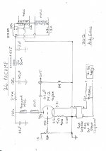
Here's another schematic - this time the low-impedance - but low-cost solution!
This is the version of filament bias we developed, using a IDHT cathode follower - with its heater soaking up the filament bias heat - and saving the trouble of an extra heater supply!
The 6H6 has a 6.3V 750mA heater, and 2 in parallel give 22mA/V, which translates into a cable-drive impedance of 45 ohms !! Enough to drive the worst kind of long cable.
Attachments
Output to S&B TX-102 TVC.Any more schematics?
Attachments
Last edited:
Hi Andy,
In post 1941 above you set the anode voltage to 98V, with 12 VDC as a heater voltage input to the Coleman reg and a 5 ohm/40W resistor.
Last year you mentioned for the 26 an anode voltage of 138V, with 16 VDC as a heater voltage input to the Coleman reg and a 10 ohm/50W resistor.
Can you please expand on the difference, as both designs used the double 156C? Was it just a difference in available mains transformer voltages, or is the one above a further development with audible improvement?
Hi!
you were going with 7k source impedance into a TVC?
Even with a TVC for high impedance drive, I would not consider this as optimal
Thomas
Output to S&B TX-102 TVC.
you were going with 7k source impedance into a TVC?
Even with a TVC for high impedance drive, I would not consider this as optimal
Thomas
Hi Thomas!
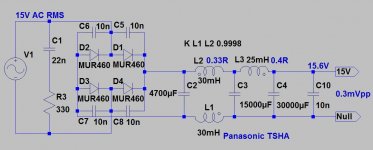
I now, it's not optimal.....but sounds amazing.
Tx-102 (400H, 100pF) simulated impedance graph (as TVC).
Some discussion:
http://www.diyaudio.com/forums/parts/48181-how-build-pre-using-s-b-tx-102-transformers-20.html
My measuring: upper -3dB point above 300kHz!
I now, it's not optimal.....but sounds amazing.
Tx-102 (400H, 100pF) simulated impedance graph (as TVC).
Some discussion:
http://www.diyaudio.com/forums/parts/48181-how-build-pre-using-s-b-tx-102-transformers-20.html
My measuring: upper -3dB point above 300kHz!
Attachments
Last edited:
Hi!
you were going with 7k source impedance into a TVC?
Even with a TVC for high impedance drive, I would not consider this as optimal
Thomas
I'll be trying something similar using Slagle autoformers in a parafeed setup. The nickel laminations can be stacked to give up to 190H inductance. I plan to try out the 26 plate output directly into the autoformers as well as the mu output from the plate CCS (should be ~1500ohm). I figure that it can't hurt to try running directly into the volume control before sticking a transformer in between.
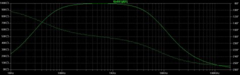
I've read that others have tried and failed using a CCS mu output into a parafeed output due to oscillations, but my sims show that with the right "lossy parafeed" setup the LF peaking can be very well controlled. I've attached a plot showing the LF response and the core drive figure of merit, using the autoformer stacked 3x3 (~150H) for regular parafeed (dark blue trace) and lossy parafeed. The extreme LF peaking is greatly reduced using the LPF setup, and the -3dB point is lowered. We'll see how that works out in real life...
P.S.: My two aluminum chassis (PSU and Preamp) are finally in the manufacturing process at Front Panel Express and should be done within 5 working days - Yeah!!
.
Attachments
Last edited:
Hi,Output to S&B TX-102 TVC.
I build pre-amp,
I have a question:
1. Why should (SSHV + CCS + Preamp)? I understand it - the sound is good, very little noise is 120Hz, Out THD is very small ... but
2. If you can only use (CCS + Preamp) - we have too - sounds good, Out THD is very small ...
3. use in the anode Cascode CCS (DN2540) - we always have - the sound is good, Out THD is very small (almost perfect) ... good rejection of power supply ...
what improvements we have with the scheme (SSHV + CCS + Preamp),
when compared with (Girator + CCS + Preamp)?
any thoughts on this? Why complicate things?
Vyacheslav.
I am about to begin a 26 linestage ...
got a bounch of tubes, sshv2 and waiting for rods regulators ...
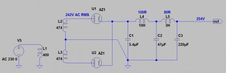
havent yet decided about the b+ ps, whether its gonna be ss or tube rectifier, and if its gonna be tube ... which tube ....
I have one question, apart from the LL1660 and Thomas new LL2745 (8ma) are there any other ot suggestions to look at?
thanks !
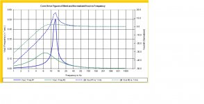
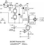
Pretty much I'll follow this schematic by Rod
got a bounch of tubes, sshv2 and waiting for rods regulators ...
havent yet decided about the b+ ps, whether its gonna be ss or tube rectifier, and if its gonna be tube ... which tube ....
I have one question, apart from the LL1660 and Thomas new LL2745 (8ma) are there any other ot suggestions to look at?
thanks !
Pretty much I'll follow this schematic by Rod
Attachments
I am about to begin a 26 linestage ...
got a bounch of tubes, sshv2 and waiting for rods regulators ...
havent yet decided about the b+ ps, whether its gonna be ss or tube rectifier, and if its gonna be tube ... which tube ....
I have one question, apart from the LL1660 and Thomas new LL2745 (8ma) are there any other ot suggestions to look at?
thanks !
Pretty much I'll follow this schematic by Rod
Hi Dmitris,
Transformer output is excellent choice in many ways - but the transformer must be a very high quality part to do justice to the 26 line amp.
The LL1660 certainly meets the requirements, but the cost is quite high. Maybe others have tried different high quality trafos - anyone??
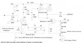
The alternative is some kind of cathode follower to give the necessary high-drive, low output impedance to suit cable-driving.
Here's another circuit combining filament bias and a cathode follower - with the heater of the 6N6 forming the load of the filament bias for the 26 (saving you a heater supply). This should give very good sound for the cost!
.
Attachments

Gyrator with mu-follower output provides low output impedance. Good output cap and is a very simple and cost effective preamp...next step, as Rod suggested, you can add a source follower to increase the current driving capability...
Good filament bias preferd and quiet HT supply is required of course...
Ale
Good filament bias preferd and quiet HT supply is required of course...
Ale
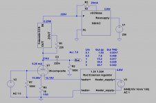
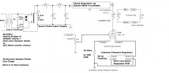
I've been testing the LL2745 OT in the workbench and now am planning to build the following incarnation of the 26 preamp. I will use the Gary Pimm's approach to CCS+VR as HT. I have done some tests recently and they perform really well (i.e. over 60dB attenuation at 50Hz). I'm re-using the HT and LT raw supplies but luckily can try the operating point that found in the workbench to be quite good for the 26 (after previous tests and preamps versions).
I don't have at the moment a balanced input amp, however I'd like to leave this preamp ready for future push-pull amp project which may have a balanced input. I can then wire a special set of cables with the pins 2 and 3 only...
thoughts?
Ale
I don't have at the moment a balanced input amp, however I'd like to leave this preamp ready for future push-pull amp project which may have a balanced input. I can then wire a special set of cables with the pins 2 and 3 only...
thoughts?
Ale
Attachments
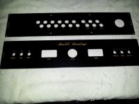
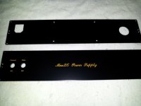
Just received the panels from Front Panel Express. Everything came out great except for one minor glitch...the bottom panels were chromated on the wrong side...we're working that one out. The chromating gives a corrosion-free finish so I can use the bottom panels as ground planes. Other than that they look great! I've attached snapshots of the front and back panels of the linestage and power supply.
The front panels are 5mm thick aluminum, the back are 2.5mm thick aluminum. All are powder coated in jet black and engraved with ochre brown infill. The cutouts line up perfectly with the Bent Audio control and input selector panels, too.
The top panels of both units have been dropped off at a local plating shop for triple chrome plating to a mirror finish for that extra little bling.
Once I get the bottoms straightened out the build can be completed, hopefully within the next 2 weeks!
Attachments
- Home
- Amplifiers
- Tubes / Valves
- #26 pre amp