Interesting link RodFor my part, I enjoy working with over-rated trafos, but maybe the chassis will wind up being very large.
If you would like 250V dc raw supply before the VR tubes, then my best recommendation would be to start with about 330V rms secondary with 150VA rating, and then use choke-input configured supply. With a valve-rectifier and choke input filter, you will get 260 to 280V dc raw output - and you can fine-tune this by using Duncan PSUD2 software.
I use industrial isolation transformers for this task, because the cost is low.
In the UK this means JMS:
150 VA
")
Why so large though? Wouldn't even a 75VA trafo be well overspecced?
It sounds like I should stay with the big transformers? No problem I have enough of them and two separate power supply chassis will make it lighter than one mega chassis with all the transformers on it.
I think that if you can raise the raw dc voltage required, then build with the transformers you have. If you really enjoy the preamp, you can upgrade the trafo, or if you want to try another power supply design, eg shunt regulated (SSHV), you can design-in the right trafo for the job.
Plenty of room on the chassis means you can try out different things later.
Interesting link Rod
Why so large though? Wouldn't even a 75VA trafo be well overspecced?
I think the 150VA is the smallest size of JMS that is clearly visible as a split-bobbin design. The smaller clamp-mounted trafos may have the secondary wound directly on top of the mains primary - meaning much higher inter-winding capacitance. For a preamp, the mains trafo should have the lowest possible primary-secondary capacitance, and a split bobbin design keeps it to about 70pF, even at 150VA and 330V (measured on JMS builds).
An electrostatic screen makes an even better solution - but at a higher cost.
Ah, I see, thanks Rod. Presumably low primary-secondary capacitance is good for output stages too? Eventually I'll box-up my 26-10Y-300B amp which currently has two mono power supplies because of weight and the iron I had to hand. But one option is to use a single large mains trafo, 300VA perhaps, or larger even. That would give plenty of scope for playing around with a shunt reg for the 26s too.I think the 150VA is the smallest size of JMS that is clearly visible as a split-bobbin design. The smaller clamp-mounted trafos may have the secondary wound directly on top of the mains primary - meaning much higher inter-winding capacitance. For a preamp, the mains trafo should have the lowest possible primary-secondary capacitance, and a split bobbin design keeps it to about 70pF, even at 150VA and 330V (measured on JMS builds).
An electrostatic screen makes an even better solution - but at a higher cost.
Starved Filaments on #26 Tubes
Has anyone seen this work by Steve Bench re: starved filaments on DHTs? It appears that drastically reducing the voltage on DHT filaments (#26 included) can result in much lower distortion in small signal applications such as preamps.
Anyone ever give this a try?
DHT with starved filaments.
Has anyone seen this work by Steve Bench re: starved filaments on DHTs? It appears that drastically reducing the voltage on DHT filaments (#26 included) can result in much lower distortion in small signal applications such as preamps.
Anyone ever give this a try?
DHT with starved filaments.
I have a question concerning R6's value on the Rod Coleman heater kit. The paper with the parts count and values list R6's value of 150 ohms. The paperwork shows 330 ohms. Which do I use for the #26?
It is a very nice compact neatly designed board in my opinion. It only took about 15min to put them both together. I can hardly wait for the weekend to start on the power supply.
It is a very nice compact neatly designed board in my opinion. It only took about 15min to put them both together. I can hardly wait for the weekend to start on the power supply.
I have a question concerning R6's value on the Rod Coleman heater kit. The paper with the parts count and values list R6's value of 150 ohms. The paperwork shows 330 ohms. Which do I use for the #26?
It is a very nice compact neatly designed board in my opinion. It only took about 15min to put them both together. I can hardly wait for the weekend to start on the power supply.
Hi Joe,
Looks like a slip with the delivery note.
With your kits, please use R6 = 330. This should be present in the kit.
I hope you enjoy the sound with them!
Accessories for DIY audio projects
Two Terminal Constant Current Source
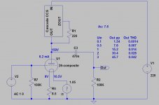
These products were developed based on the Supertex DN2540N5 and IXYS IXTP01N100D depletion mode MOSFETs to enable constant current operation of tube circuits without having to worry about a source of bias. They are very simple and easy to integrate into existing designs. Use current sources to provide excellent balance in "long-tail" pair differential circuits or to obtain highly linear constant current triode operation as a plate load. Add a heat sink kit for operation at higher levels of power dissipation. Three versions are offered: an economical basic current source with very good performance, a cascode current source for improved measured performance and a slight sonic improvement, and a compact cascode current source that can be used to replace resistors for easy upgrading to constant current operation. These kits feature current adjustability over a wide range (2.5mA to 100mA) and space for a fixed resistor to replace the variable resistor once the “correct” current has been determined. The minimum operating voltage is 4VDC + 1/2 peak-to-peak AC signal amplitude and the voltage rating maximum is 1000VDC.
Current source kit
Cascode current source kit
Compact Cascode current source kit
Basic Current Source Kit (up to 1.5 watts) $8
Cascode Current Source Kit (up to 1.5 watts) $12
Small Heat Sink Kit (up to 4 watts) $3
Large Heat Sink Kit (up to 7 watts) $3.50
Compact Current Source Kit (up to 3 watts w/included heat sink) $14
Large Cascode Current Source Kit (up to 7 watts w/included heat sink) $18
Which kits should I purchase?
Two Terminal Constant Current Source
These products were developed based on the Supertex DN2540N5 and IXYS IXTP01N100D depletion mode MOSFETs to enable constant current operation of tube circuits without having to worry about a source of bias. They are very simple and easy to integrate into existing designs. Use current sources to provide excellent balance in "long-tail" pair differential circuits or to obtain highly linear constant current triode operation as a plate load. Add a heat sink kit for operation at higher levels of power dissipation. Three versions are offered: an economical basic current source with very good performance, a cascode current source for improved measured performance and a slight sonic improvement, and a compact cascode current source that can be used to replace resistors for easy upgrading to constant current operation. These kits feature current adjustability over a wide range (2.5mA to 100mA) and space for a fixed resistor to replace the variable resistor once the “correct” current has been determined. The minimum operating voltage is 4VDC + 1/2 peak-to-peak AC signal amplitude and the voltage rating maximum is 1000VDC.
Current source kit
Cascode current source kit
Compact Cascode current source kit
Basic Current Source Kit (up to 1.5 watts) $8
Cascode Current Source Kit (up to 1.5 watts) $12
Small Heat Sink Kit (up to 4 watts) $3
Large Heat Sink Kit (up to 7 watts) $3.50
Compact Current Source Kit (up to 3 watts w/included heat sink) $14
Large Cascode Current Source Kit (up to 7 watts w/included heat sink) $18
Which kits should I purchase?
I was going to use a CCS in each power supply prior to the voltage regulator tubes I will be using. I plan a choke before the plate. I just wanted to know which unit to purchase because I would like something on a pre made PC board so I don't have to make something up. Since I am making two power supplies one for each mono block line stage channel. I have no experience with these CCS's and for that matter I have never used one in anything and would like to purchase the correct one the first time around.
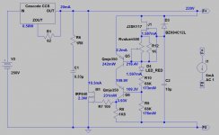
SSHV2 for type 26.
http://www.diyaudio.com/forums/power-supplies/134801-simplistic-mosfet-hv-shunt-regs-263.html
http://www.diyaudio.com/forums/power-supplies/134801-simplistic-mosfet-hv-shunt-regs-263.html
Attachments
I think I remember mentioning that I was going to use VR tubes for shunt regulation. I know that I received several comments to the fact that they are noisy. Well I have a thread about rectifier tubes sounding different and there is a post a reference to the Ammnity Raven and something else. Anyway there is a comment on VR tubes which I will quote here
A deluxe feature, which was easy to add, is the Voltage Regulator (VR) tube shunt-regulation for the driver. I wanted to drop 270 volts, so why not regulate at the same time? The noise of VR tubes is only 1mV of very smooth broadband noise, while the more common Zener diodes have 3 to 5mV of spectrally nonflat noise, occasional LF bumps and pops from "popcorn" noise, problems with temperature coefficients, and a huge amount of grossly nonlinear capacitance. Zener diodes need a lot of filtering and additional circuitry to isolate the problems. By contrast, VR tubes need no additional circuitry at all - just keep them away from capacitive loads.
So why are VR tubes frowned upon so much and why wouldn't they be a good element to use in a #26 line stage?
Ok, so if I use a power supply with some ripple and I run it thru a cascoded DN2450 CCS and then a VR shunt regulator stage I should come out with a ripple of 1mv or so. At this point would I not be good to go for a choke loaded #26. Would I be better off to ditch the choke and go thru another CCS and then the #26's plate?
There is an article on "Minimun Reactance Power Supply" at Chapter 5
It says I could have 100 volts of ripple and as long as the stayed above the 220v the CCS would reject all the ripple. They are saying they want to maintain 200 volts on the output.
So if I used a CCS before my VR tubes and a CCS to feed the plate of the #26 I would have 0 ripple at the plate of the #26? Is this correct?
I'm not sure use two CCS's this way, they will fight one another with tempeature dift and oscillate unless the first one is much bigger than the sond?
The problem wih the VR tubes is hiss, you can filter it out with a big eletrolytic in paralell but then you have a big electrolytic in the signal path and reportedly a cheap cap sounds like a cheap cap and a BG sounds like a BG, defeats the purpose of a shunt, also the output impedance of the vr tubes is high for a powersupply. See the epc audio electric avenue project.
For low noise regulation the sshv is tough to beat, there is a new group buy for version 2 forming.
- Home
- Amplifiers
- Tubes / Valves
- #26 pre amp