You mean the Zeus output stage?
It is part of Susan Parker's design; you will find a long thread at this forum.
The output stage is a transformer coupled design, actually nothing special topology wise; it does not depend on one particular type of power fet.
Thanks, the thing I like about the concept it is even though you still have an output transformer, you don't loose the gain the typical tube OPT ratio gives, so it saves you an extra tube gain (which may or may not significantly increase distortion.) Also there must be a means to dc servo CCS's to the mofsets before the opt so that primary current is a non issue . So for preamp output levels the quality of the transformer could be much better (small permalloy core, lower ratio, almost impossible to find a 15k:60/32 ohm OPT with this sort of transperancy.)
Hi Rod - please remain off topic! I think for a few of us it's worth going through options of what we connect our 26 preamps onwards to.
I can see the LSK170, 2SK369 and the 2SK170 - are they all still obtainable? Do you see these as good SE choices directly after the 26 stage to use into a transformer to do the phase splitting? I'm also thinking PP2a3 here.
Presumably a 2SK170 stage would give low output impedence and allow a transformer volume control. This is getting into Thomas Mayer's territory.
andy
Hi Andy. I assume you're interested in zero-feedback circuits - otherwise there's many feedback-buffers on the SS forum, I imagine.
If you just want to stiffen up the output impedance of your 26 preamp, usually a transformer would be a good choice. But if you want to experiment with low-cost SS circuits, the 2SK369 does have amazing performance.
Low impedance and capacitor-coupling is a bad combination, but achieving zero offset requires some kind of servo. Well, why not. You don't need an op-amp, you can use a friendly low-capacitance MOS like the BSS138 (SMD) or BS108.
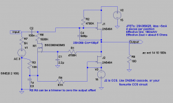
Here is an idea for a buffer using multiple parallel 2SK369 for driving a TVC or splitter transformer. All you have to do is work out the minimum load impedance, and the maximum voltage swing you need. That will give you the class-A current required for a JFET buffer stage.
for example, say you want to drive 10V peaks into 600 ohms - that's about 16mA peaks. 4x or 5x 2SK369 at 5mA Idss will supply those peaks amply. You can go on adding K369s in parallel to get any current peak you like, but calculate the rolloff from the output impedance of the preamp with the circuit capacitance.
The 2SK369 (Green grade, Idss about 5mA) was still available last time I looked. They give 40mA/V at 5mA, so 4 in parallel give you 160mA/V, with an output impedance of about 6 ohms. This is with zero feedback!
The attached diagram gives a circuit idea, complete with offset-nulling servo in M1. You have to make R3:R4 into a trimmer to zero out the offset. The 26 output impedance is modelled by the 5K of R7, and the 500pF C4 models 4x input capacitance (+ stray) of K369 at Idss. Even there you get out to 60kHz before dropping a dB.
THe class A stage is completed with a current-sink (shown here as J2) - use your favourite CCS circuit, or cascode a pair of K369s.
Attachments
The 2SK369 (Green grade, Idss about 5mA) was still available last time I looked. They give 40mA/V at 5mA, so 4 in parallel give you 160mA/V, with an output impedance of about 6 ohms. This is with zero feedback!
Are these used as source followers? When so, you guess my next question.
Hi Pieter, yes, J1 is source follower-connected, class A running at Idss......
OK, then there is 100% local feedback
")
I guess that with zero feedback you mean zero global feedback, but frankly all buffers use local feedback.
All devices effectively have degeneration type of feedback...
feedback across multiple gain stages is what seems to cause the problems. With degeneration (local source/cathode/emitter current derived feedback), there can be no phase shift, which may be the root of the sounds we don't like.
a follower is offered here as a tradeoff to get low drive impedance... maybe a transformer will sound better, but someone will have to do the comparison....
Agree Rod, our triodes all have degeneration feedback.
But many tube guys get nervous when feedback is mentioned, not realizing that there is always feedback somewhere.
I understand you meant zero global NFB in your post #1442.
As for a comparison between SS buffers (or tube buffers for the same reason) and transformer step-down I would choose the better sounding option of course, also if it turns out to be with the buffer. Big advantage for the transformer is that no coupling capacitors are needed.
Zeus output stage
Hi,
To clarify, the particular part that has gone obsolete is a specific IXYS depletion mosfet (IXTH 20N50D) which allows for auto biasing using the DC resistance of the transformer windings.
There are other depletion power fets from IXYS and others, but their turn on characteristics are not suitable for this application with the specific output transformer I use.
Personally I like the depletion parts for the extreme simplicity as they allow for the audio path with everything hard ground referenced. A complete audio system with four transformers, three mosfets (and three protection zeners), three gate resistors and two termination resistors in the audio path is nice and straightforward.
However using standard, lateral or other positive turn on mosfets is fine. This just needs an additional bias supply to get the mosfets turned on.
Anything from an IRF150 works as long as it has the voltage rating (must be comfortably more than TWICE the power supply rail) with suitable current and power dissipation capability as they are used in analogue mode, not as switches.
Some mosfets work better than others of course, but it is a matter of smaller degrees rather than huge go/no-go situations.
In my experience the laterals are more prone to HF oscillation, which is cured with ferrite beads close to the source pins.
Using a hybrid topology one has the advantage of the tube front end with the sand based Zeus follower output stage which will not affect the tonal quality of the tube stage(s) but give the extra grunt needed to drive the more demanding speaker loads.
And a final note, the gate protection zeners MUST be used AT ALL times. A few mosfets have them built in, most don't. Buy lots of zeners (they are cheep). Solder them on from the get go, and always leave them attached when swapping parts around.
Best wishes,
Susan.
Hi,
... But speaking of unobtainable, I thought the zeus output was no longer an option as the mosfets are specific and obsolete, I did search but couldn't find that thread (not on SS much.)
To clarify, the particular part that has gone obsolete is a specific IXYS depletion mosfet (IXTH 20N50D) which allows for auto biasing using the DC resistance of the transformer windings.
There are other depletion power fets from IXYS and others, but their turn on characteristics are not suitable for this application with the specific output transformer I use.
Personally I like the depletion parts for the extreme simplicity as they allow for the audio path with everything hard ground referenced. A complete audio system with four transformers, three mosfets (and three protection zeners), three gate resistors and two termination resistors in the audio path is nice and straightforward.
However using standard, lateral or other positive turn on mosfets is fine. This just needs an additional bias supply to get the mosfets turned on.
Anything from an IRF150 works as long as it has the voltage rating (must be comfortably more than TWICE the power supply rail) with suitable current and power dissipation capability as they are used in analogue mode, not as switches.
Some mosfets work better than others of course, but it is a matter of smaller degrees rather than huge go/no-go situations.
In my experience the laterals are more prone to HF oscillation, which is cured with ferrite beads close to the source pins.
Using a hybrid topology one has the advantage of the tube front end with the sand based Zeus follower output stage which will not affect the tonal quality of the tube stage(s) but give the extra grunt needed to drive the more demanding speaker loads.
And a final note, the gate protection zeners MUST be used AT ALL times. A few mosfets have them built in, most don't. Buy lots of zeners (they are cheep). Solder them on from the get go, and always leave them attached when swapping parts around.
Best wishes,
Susan.
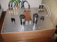
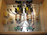
One more #26 pre finished.
This time I used filament bias, instead of battery. Getting rid of the input cap was nice. Also, ll1660pp output transformers, Intact audio autoformers at the output for volume control. Heater regulators by Rod, and double latest Salas design SSHV2 for voltage regulation.
There is big change in sound to the better from the one I had before with battery bias. Mainly it seems clearer and more dynamic. I like it a lot!
Attachments
One more #26 pre finished.
This time I used filament bias, instead of battery. Getting rid of the input cap was nice. Also, ll1660pp output transformers, Intact audio autoformers at the output for volume control. Heater regulators by Rod, and double latest Salas design SSHV2 for voltage regulation.
There is big change in sound to the better from the one I had before with battery bias. Mainly it seems clearer and more dynamic. I like it a lot!
With Rod's kits the filament bias seems the way to go, I mean you eliminate an input transformer/cap and don't need a cathode bypass cap, I imagine there is a limit to how much vou can have across the regulator outputs as far as using the cathode resistor in series with the cathode as the load ?
Rod can tell you more about the limits of his regulators. In my build, I have vin 17.5V and 11.4Vout.
Hi George, Looks like good layout and build!
Voltage Rating for Filament Bias:
With correctly specified C1 and R8, any new kit can be configured to run Filament bias up to 45V or so at the input.
With changes of transistor 200V is possible - though I can't imagine it is needed.
Flexible operating voltage - the beauty of discrete-transistor design! New V4 kits are available for Filament bias.
One more #26 pre finished.
This time I used filament bias, instead of battery. Getting rid of the input cap was nice. Also, ll1660pp output transformers, Intact audio autoformers at the output for volume control. Heater regulators by Rod, and double latest Salas design SSHV2 for voltage regulation.
There is big change in sound to the better from the one I had before with battery bias. Mainly it seems clearer and more dynamic. I like it a lot!
Wow George, there is more difference using one or two SSHV2 regs instead one?
- Home
- Amplifiers
- Tubes / Valves
- #26 pre amp