I'm a little bit lost about best sound schematic, could anybody help me please?
Felipe,
There are many variations in this thread. The 'best sounding' is a bit personal and also will depends on your power supply and end to end system. Difficult one to answer. What are you looking for: CCS, choke, OT?
Andy Evans posted the choke version with an AZ1 hybrid power supply which is the result of a long search for what sounded best for him. I suggest you start with that one and modify it once you build it and listen to the results.
I haven't finished mine, so don't have full schematics and still need to do many listening tests to come with my final version.
Cheers,
Ale
Difficult to say the best sound, since we haven't had a "shootout"! I think many of us have tried many, many different versions. My final decision was:
- choke load or transformer, both possible. I preferred these to active loads or resistors
- choke input power supply, at least LCLC - small input cap useful.
- all PSU capacitors polypropylene
- Nice rectifier - AZ1 mesh best followed by 80.
- Filament bias. Keeps cathode close to ground and eliminates the input cap needed with grid battery bias, which was next best option
- Choke input (or small cap e.g. 220uF) for filament supply.
- Good DC supply, e.g. Rod Coleman's boards
- globe 26s.
I haven't found anything that sounds better. Obviously the output transformer or plate choke can be as good as you can afford - amorphous, nickel, handmade etc.
Andy
One question regarding the power supply choke orientation. I have two 20H chokes part of an CLCLC stage for the raw HT supply and I'm planning to mount them on the top plate. Can I put them in parallel or do I need to orientate them in 90 degrees between each other?
90°
Hi Ale,
No need to worry about choke orientation in this case. Since you have a C-input filter, the AC across the first choke is already greatly attenuated. In general chokes in such a configuration are not very prone to pick up stray fields. And even if, it is minor and not very critical since you have another filter or regulator downstream at the preamp.
You would benefit more to orient the core of the chokes 90 degree against the power transformer.
But again, don't worry too much here. More important to keep the chokes and PT away from your output transformers
Best regards
Thomas
IOne question regarding the power supply choke orientation. I have two 20H chokes part of an CLCLC stage for the raw HT supply and I'm planning to mount them on the top plate. Can I put them in parallel or do I need to orientate them in 90 degrees between each other?
No need to worry about choke orientation in this case. Since you have a C-input filter, the AC across the first choke is already greatly attenuated. In general chokes in such a configuration are not very prone to pick up stray fields. And even if, it is minor and not very critical since you have another filter or regulator downstream at the preamp.
You would benefit more to orient the core of the chokes 90 degree against the power transformer.
But again, don't worry too much here. More important to keep the chokes and PT away from your output transformers
Best regards
Thomas
Hi everyone, first time poster but after coming across this thread I'll probably be more active haha. I had no idea there was such an active fan base for the 26, I built one recently too and fell in love instantly. I found this thread by googling about some filament supply chokes and I've spent hours reading since. I actually had this huge long post written about my experiences with my 26, it was long, it was funny, it had life and love and death, it was long, complete with critiques and opinions about various techniques and components, laughter, sadness, but mostly it was long.. you get the point haha. But after hitting submit it said I wasn't logged in so I lost everything I wrote :\ Maybe I'll rewrite it another time, for now I'll just ask a question so I can go to bed.
Anyone ever try the hammond 159ZA for choke input filament? I'd like to get it for the 300mH but not sure if I'm cutting it too close to the rated current. I'd like to think it could handle its rated value and maybe a little more given the low voltage but I'm not sure. A custom/high quality choke probably could but for the hammond I had to ask first. Anyone ever use this for the 26 filament and had any problems? Can't afford anything better at the moment but all suggestions welcome.
Thanks! Glad to find this place.
-Charles
Welcome to the forum.
Too bad you lost your longer message. I've learned my lesson the hard way too. Now, when I write a message that would require some significant time/effort to re-write, I always do a select-all & copy before hitting submit.
Can't comment on the use of that particular Hammond choke, but here's my experience with the filament supply. I started with a CLC filter driving a cascoded mosfet current limiter/capacitor multiplier circuit. The choke was a vintage Hammond (no model on it), rated at 2A and 106mH, the capacitors 30mF each. However, after some tinkering I got more confidence in the line rejection of the capacitor multiplier and pulled out the LC and left on only one 30mF capacitor, before the multiplier. The scope shows just as much ripple on the filament without the choke, as there was with the choke. Of course, it's all due to the current limiter/cap multiplier.
Starting 26 preamp
Thank you guys,
I have on hand to make my first attempt for 26 in two separate boxes:
PSU CLC
B+
-1 Power tx one secondary 150V 100W Bartolucci
-1 Choke 10H 100mA 200VDC
-2 40uF 440VAC ASC X386S polypropylene in oil
-1 power tx dual secondary 6V total 12VA
-1 AZ1 with two diodes for rectification (two 1R in cathodes)
-1 Salas HV shunt regulator
HEATERS
-2 power tx dual secondary 6V total 2 secondaries 50VA
-2 Rod Coleman regs.
PREAMP
-2 Lundhal LL1660
-2 TVC
-1 Switch four decks
-2 Tubes 26 ST
-1 9V Alkaline for Battery Bias
Due the complexity of project I wanna be sure of the schematic that I have to be done:
-As per Thomas Mayer advice using the TVC input cap can be suppressed.
-About Battery Bias I see different ways to implement: one connecting battery positive to gnd and after to pin 4 filament negative of 26 tube (coolzero) & other connecting the battery negative to 220K and battery positive to ground (Rod Coleman), wich one is the best assuming I don't will use volume pot at the input because as per I understood my TVC must be connected between step-down transformer LL1660 & power amp input?
-I see Andyjevans using only 1K resistor to grid after 100k volume pot without any cap, coolzero same adding 0,15uF between the 100k volume pot and 1k grid resistor & Rod Coleman only using a 220nF cap between the volume pot & the grid, wich one have I to use if I don't use volume pot at the input?
-About Rod Coleman heaters I see Andyjevans uses 10R 50W between the negative Rod's filament heater and filament also is connected to gnd between the reg & the resistor. Rod only connect his filament heater & the negative filament to gnd?
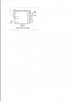
-LL1660 must be wired as per attached pic?
All help will welcome.
Felipe,
There are many variations in this thread. The 'best sounding' is a bit personal and also will depends on your power supply and end to end system. Difficult one to answer. What are you looking for: CCS, choke, OT?
Andy Evans posted the choke version with an AZ1 hybrid power supply which is the result of a long search for what sounded best for him. I suggest you start with that one and modify it once you build it and listen to the results.
I haven't finished mine, so don't have full schematics and still need to do many listening tests to come with my final version.
Cheers,
Ale
Difficult to say the best sound, since we haven't had a "shootout"! I think many of us have tried many, many different versions. My final decision was:
- choke load or transformer, both possible. I preferred these to active loads or resistors
- choke input power supply, at least LCLC - small input cap useful.
- all PSU capacitors polypropylene
- Nice rectifier - AZ1 mesh best followed by 80.
- Filament bias. Keeps cathode close to ground and eliminates the input cap needed with grid battery bias, which was next best option
- Choke input (or small cap e.g. 220uF) for filament supply.
- Good DC supply, e.g. Rod Coleman's boards
- globe 26s.
I haven't found anything that sounds better. Obviously the output transformer or plate choke can be as good as you can afford - amorphous, nickel, handmade etc.
Andy
Thank you guys,
I have on hand to make my first attempt for 26 in two separate boxes:
PSU CLC
B+
-1 Power tx one secondary 150V 100W Bartolucci
-1 Choke 10H 100mA 200VDC
-2 40uF 440VAC ASC X386S polypropylene in oil
-1 power tx dual secondary 6V total 12VA
-1 AZ1 with two diodes for rectification (two 1R in cathodes)
-1 Salas HV shunt regulator
HEATERS
-2 power tx dual secondary 6V total 2 secondaries 50VA
-2 Rod Coleman regs.
PREAMP
-2 Lundhal LL1660
-2 TVC
-1 Switch four decks
-2 Tubes 26 ST
-1 9V Alkaline for Battery Bias
Due the complexity of project I wanna be sure of the schematic that I have to be done:
-As per Thomas Mayer advice using the TVC input cap can be suppressed.
-About Battery Bias I see different ways to implement: one connecting battery positive to gnd and after to pin 4 filament negative of 26 tube (coolzero) & other connecting the battery negative to 220K and battery positive to ground (Rod Coleman), wich one is the best assuming I don't will use volume pot at the input because as per I understood my TVC must be connected between step-down transformer LL1660 & power amp input?
-I see Andyjevans using only 1K resistor to grid after 100k volume pot without any cap, coolzero same adding 0,15uF between the 100k volume pot and 1k grid resistor & Rod Coleman only using a 220nF cap between the volume pot & the grid, wich one have I to use if I don't use volume pot at the input?
-About Rod Coleman heaters I see Andyjevans uses 10R 50W between the negative Rod's filament heater and filament also is connected to gnd between the reg & the resistor. Rod only connect his filament heater & the negative filament to gnd?
-LL1660 must be wired as per attached pic?
All help will welcome.
Attachments
-About Rod Coleman heaters I see Andyjevans uses 10R 50W between the negative Rod's filament heater and filament also is connected to gnd between the reg & the resistor. Rod only connect his filament heater & the negative filament to gnd?>>
This is filament bias, which is quite different from cathode bias.
Andy
This is filament bias, which is quite different from cathode bias.
Andy
Hi!
Best regards
Thomas
Not sure what you mean with this, the TVC has nothing to do with the input cap. You won't need an input cap on the power amp since your preamp has a transformer output and thus is free of any DC offset.As per Thomas Mayer advice using the TVC input cap can be suppressed.
Yes, place it at the output of the preamp.I understood my TVC must be connected between step-down transformer LL1660 & power amp input?
Yes-LL1660 must be wired as per attached pic?
Best regards
Thomas
Hi!
Not sure what you mean with this, the TVC has nothing to do with the input cap. You won't need an input cap on the power amp since your preamp has a transformer output and thus is free of any DC offset.
Best regards
Thomas
Many thanks for input Thomas, I'm explained very bad, I wanna said if can avoid the input cap of 26 tube preamp?
Best
Felipe
Hi Thomas,
That's the problem I don't have a definitive circuit to start, if possible I prefer to avoid caps in the signal path, only schematic posted without input cap is Andyjevans & don't use battery bias but uses filament bias with 10R 50W so I need to buy the resistors & change the power tx for heaters and a couple of lytics in Rod Coleman heaters to increase till 35V the caps, worth the money or better do the first attempt with input cap?
Thanks for help & the best
Felipe
Hi!
For a first attempt I would do just normal cathode bias. Once that works you can experiment from there
Thomas
Thanks for all support Thomas.
Felipe
Hi Thomas,
That's the problem I don't have a definitive circuit to start, if possible I prefer to avoid caps in the signal path, only schematic posted without input cap is Andyjevans & don't use battery bias but uses filament bias with 10R 50W so I need to buy the resistors & change the power tx for heaters and a couple of lytics in Rod Coleman heaters to increase till 35V the caps, worth the money or better do the first attempt with input cap?
Thanks for help & the best
Felipe
Hi Felipe,
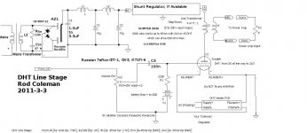
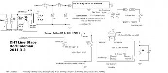
This is the schematic I use for starting work on a Line Amp. I have drawn it with Battery bias, and Kathode bias versions. Maybe you can use this to start your own schematic?
You will have to decide a value for the rectifier capacitor [C4]. Wire the transformer, rectifier, chokes, capacitors, then try the power supply and change C4 until you get the right voltage you need. This capacitor should be 4.7uF or less, or the rectifier will suffer.
When you are happy with the supply voltage, you can adjust Rk to get the operating current in the 26 (Kathode bias version).
Connecting the Filament Regulator: For Kathode or battery bias version, the filament regulator FIL+ terminal connects to the Kathode resistor, or Ground (battery version).
(With Filament bias, it's the -ve terminal).
Please make sure there are no hum-pots, or ANY other wiring to the filament regulator. If you can wire it like this, the preamp will be completely quiet, and sound wonderful!
.
Attachments
Hi Rod,
I always see snubbers across secondaries in you schematics. How do you determine the values of R and C? Is there a rule of thumb, or do you measure by scope what is optimal.
Have you ever listened to the effects of snubbers? I mean are they there for better measured performance or for better sound quality (or both!)?
Peter
Hi Peter, When the rectifier conducts (and when it blocks) the current waveform in the trafo-rectif-cap circuit might have steep edges.
But, we know that the transformer is inductive - we have an LC tuned circuit! This can make the current with a large resonant peak, which might be coupled into the signal wiring ( by conduction, or by radiation).
A series R-C circuit will provide damping, to control the current peak. To make an accurate snubber, you must make a current probe (ferrite toroidus with a few turns... rectifier lead goes in the toroid centre-hole). Adjust the R and C until the current waveform in minimized at turn-OFF).
Measuring voltage is not much help, the current probe is needed.
The R & C values depend upon the transformer inductance - but with most trafos, 47nF to 220nF and 47 to 100 ohms will reduce the kick-back waveform quite well.
I find that even small changes to remove high-frequency noise in an amp make a big difference to the sound. This is even more important, if the transformer/rectifier/caps are not fully shielded from the signal stages of the amp.
It's exactly the same with the Filament Regulators - every small reduction in high-frequency noise can be heard. DC heating solutions that fail to tackle this problem will sound worse than ac heating!
Interesting stuff Rod! Thanks for clarifying!
I will make a current probe from a ferrite toroid and will de some measurements and listening tests.
This method is unfortunately not suitable for bridge rectifiers since the measurements are taken from the anode or cathode lead of one of the diodes. Is it also possible to measure this phenomenon with a current probe around one leads of the transformer secondaries?
Peter
Hi Peter, please try measuring current in the trafo lead, and maybe also in the capacitor (after the rectifier -C4 in my schematic above).
Please make sure that the wiring between the rectifier/trafo/capacitor is short - this reduces radiation. The measurement will be easier, and the sound of the amp will be better!
Please make sure that the wiring between the rectifier/trafo/capacitor is short - this reduces radiation. The measurement will be easier, and the sound of the amp will be better!
- Home
- Amplifiers
- Tubes / Valves
- #26 pre amp