Erwin, what's the current rating on the chokes? This will tell you whether shared chokes between L & R channel is possible or not.
Choke-input constructed B+ is definitely recommended.
Well Quasi-choke input anyway. So CLCLC, but with first cap only 0.47uF to 1.5uF (high quality polypropylene, NOT motor-run plastic-housed type). The LCR components PC/HV/S is my favourite in this position.
LCR COMPONENTS|PC/HV/S/WF 470NF 1KV|CAPACITOR, 470NF, 1000V | Farnell United Kingdom
First L should be the 10H (provided this has the highest current rating, preferably 20 - 30mA.
With 20H in the second choke position (rated 10mA+ I hope!) you can used high quality capacitors, without high values.
With that current rating, you can try it both ways. I can't be certain which way is best, but if you have noisy mains supply, then 2 chokes in the first stage might be best.
OR you could wire 10H chokes in + and - supply lines, followed by capacitor.
Then, Each channel can have a 20H choke [and a cap] to itself. you get the best of both Worlds!
OR you could wire 10H chokes in + and - supply lines, followed by capacitor.
Then, Each channel can have a 20H choke [and a cap] to itself. you get the best of both Worlds!
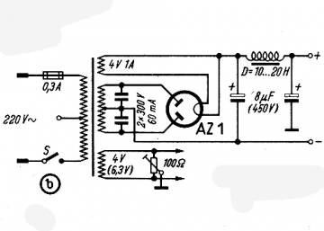
the transformer for filaments have to be 4VAC & 1.1A?
while 1A will be enough, i'd prefer go with a 1.5A minimum.
Going back to the chokes, it may be worth looking at the larger picture of preamp plus amp. I don't think separating the channels matters much - better to use the chokes for both channels combined. I don't think you need more than two chokes per supply, but polypropylene caps are important - motor runs are fine.
What I have done is make two HT supplies, each with two chokes. The lower power supply with the choke input AZ1 mesh drives the 26 preamp and the 46 driver on the amp. The higher power supply drives the 300b outputs - this is cap input 4uF and uses the 5R4GY which is the best of all the common rectifier types I've tried, though it does have bigger voltage drop. So that's where my four chokes go!
Andy
Hi coolzero,
""...Only connection for B+ negative from this rail is 470uf negative to negative (capacitor + to filament's negative and capacitor - to B+ negative)....""
In your diagram, there is already a 470uF capacitor, connected between GND and three resistors.
Did you add one more 470uF capacitor?? If so, could you show it on a diagram please??
Thankyou,
King
The diagram shown is from Jim's site (VT52.com) without a change. What I have now is completely different 26 pre with grid bias. You could find the schematic in this same thread.
while 1A will be enough, i'd prefer go with a 1.5A minimum.
It's necessary 2x300V CT 60mA Tx for B+?
It's possible only with 1x240V Tx for B+, if yes how?
Merlin, if you have two diodes only, as in that rectifier, for a full bridge you need a sec with CT or two indipendent secs.
With just one sec, you can implement a hybrid bridge: 1 tube + two ss diodes. See latest andyjevans schematic.
Edit: see post #913
Thank you Massimo, wil you see the football Champions League Final?
Maybe yes, if only I can find a Man United scarf ")
Joking aside, I saw you already asked what kind of ss diodes: 1N4007 or better rated at 1.000 V
SF4007 ultrafast/soft recovery are quite nice if you can find them. If not send me a PM with your address and I'll send you a pair.
If you want to use your AZ1 only with a proper Xfrm, pls consider that if you have a 240 V/100 mA sec (let's say), you will need a 480 V/200 mA CT or two secs 0-240V + 0-240V/100 mA each to be 100% equivalent. (That's another reasons why tubes are $$$: you need big Xfrms!)
I have on hand:
1N4007
UF4007
Fairchild 4A 600V Hyperfast II
Wich one will be the best suitable, the Fairchild right?
You are right, tubes needs a lot of iron & it's expensive, lately I bought for a friend a Tx 150VAC 100W CF125 & choke 10H 100mA MR8L from Giuseppe Bartolucci how knows to do impressive iron.
About football don't worry I only wait a very good match.
Attachments
Hi Felipe,
1N4007 has large recovery-time, and makes big current-pulse noise (difficult to measure, easy to hear)
UF4007 Fairchild works really well, just add series-RC snubber across the secondary winding:
100-ohm 0,5W carbon composition and 22nF to 47nF 1500V FKP (LCR PC/HV/S best, or PAnasonic MKP 1000V).
No need for > 1A type!
Hi Massimo, I tried some of the SF4007 - I could not find any difference in sound against UF4007, using a 300B power amp for testing
With UF4007, the recovery time is very brief, and with B+ supplies, the current pulse is quite small. Together, these properties make the recovery pulse easy to suppress with the RC-snubber.
BUT - if you have SF4007, It is always best to compare by listening, and maybe the low cost of the UF4007 made too much influence on me!
Also, the wiring around the rectifiers, snubber, secondary wiring and C1 should be short....
Hi Felipe,
1N4007 has large recovery-time, and makes big current-pulse noise (difficult to measure, easy to hear)
UF4007 Fairchild works really well, just add series-RC snubber across the secondary winding:
100-ohm 0,5W carbon composition and 22nF to 47nF 1500V FKP (LCR PC/HV/S best, or PAnasonic MKP 1000V).
No need for > 1A type!
Thanks Rod, I forgot the volts & power to use your heaters for 26, could you remember me the values?
I'm not Rod, but.....
Xfrm: 6VAC/5A (30VA)
Diodes 4x 1N5822 or MBR1045
Caps: 2x 10-15mF (I bought 12mF pana TS-UP)
Resistors: 2x 0.1-0.47 Ohm 5-7W (one for + side and one for gnd) to adjust raw dc at about 6.2-6.5 V
Sorry, I forgot to add: Xfrm must be EI with split bobbins (pri & sec), not a toroidal one.
Xfrm: 6VAC/5A (30VA)
Diodes 4x 1N5822 or MBR1045
Caps: 2x 10-15mF (I bought 12mF pana TS-UP)
Resistors: 2x 0.1-0.47 Ohm 5-7W (one for + side and one for gnd) to adjust raw dc at about 6.2-6.5 V
Sorry, I forgot to add: Xfrm must be EI with split bobbins (pri & sec), not a toroidal one.
Last edited:
- Home
- Amplifiers
- Tubes / Valves
- #26 pre amp