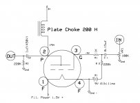
Thanks Kevin. What ever the design you have suggested initially, I still use in my pre because it works perfectly except this marginal bass response issue. I have attached the schematic here. Bass issue could be due to my SS amp and its low input impedance. When I auditioned my pre to others who are dealing with high-end systems in daily basis, they were pretty impressed however everyone noticed this lean bass response. Because it is almost near to completion of my pre, I thought of fixing this small issue as well. Below is the detail of my system (amp/speakers) to understand it full. (BTW, my speakers usually have pretty decent bass response when I played the same material without 26 pre.) I use power amp section directly to input the 26 pre.
Attachments
Last edited:
175 volts on the plate and -9v on the grid would give very high current for a 26. This may cause the lack of bass you describe?
I agree, I recommend somewhat lower plate voltage, (+150V) easily accomplished just by adding some resistance in series with the choke. Do not bypass this resistor, I think 3.3K - 3.6K would be optimum - this would also reduce the Q of the choke significantly, and may also slightly increase the effective RL at very low frequencies.
Wondering how the inductance of the choke holds up at high currents. Also if the input impedance of the amplifier is significantly below 50K ohms I would recommend increasing the coupling capacitance to 2.2uF, and below 25K to 4.7uF-5.1uF.. Loads below 20K are not recommended with choke loading - in fact 20K is a difficult load for a 26.. The current -3dB point with this power amplifier is about 6Hz, coupling cap is responsible for about -1dB at 20Hz, and the choke may be responsible for at least another dB or so..
Note that you might also want to try the 112A/12A (note the RCA-12 is a different tube!) which has an rp of around 5.1K with -9V bias and 140Vp and a filament voltage of 5V/250mA.. It would drive the amp better due its lower rp..
Last edited:
Sorry Kevin, WayneK. I have done this schematic some time back and the voltage mentioned is somewhat different from what I use now. 150V/-10V is the current parameters in place. Hope this is not a problem.
Apart from that, will there be any impact of increasing 220K resistor to higher value like 1M ? (Infact I didn't realy grab the concept out of the readings but keen to know more if you guys could explain).
Kevin, becuase my power amp input is 20K, would it help if I replace the chokes with a similar P2L Trafo of your design explained (UTC HA-133) in Positive Feedback? Or is it really necessory to look for a different tube like 112A in this situation? (I don't want to remove 26 from my setup ;*( )
Thank you guys for the knowldge share as always.
Last edited:

Kevin, your suggestion of increasing the coupling cap to 4.7u and adding 3.3k resistor in series with the plate choke was spot on. I did those changes and the result is increased bass and overall clarity significantly. you are the man.. thanks again.
Hi Kanishka,
This is good news, glad I was able to help..
Just to go back to nicoch46, news on the evolution of my 10Y filament bias preamp is that I've joined the "iron brigade". Chokes, chokes and more chokes. Better people than me worked that out a while ago and I didn't follow this path until I laid my hands on a few 280mH chokes from a local surplus outlet. I was shocked how much better choke input sounded. So out went the voltage regs in the filament supply. Thomas Mayer uses L>C>L and he's right. When I replaced the last choke with a voltage reg the sound took another nose dive. the only thing that preserved all the clarity and tone was, as stated, L>C>L. Chokes are 280mH but Hammond do a 60mH one at 2A which is probably fine. I used 10,000uF reservoir cap. This is a heavy solution, but it does avoid heatsinks and regs. And the Hammond parts are available and not expensive. I'll see if I can post a schematic. Frankly, I think this preamp is stunning.
andy
andy
Hi Kanishka,
This is good news, glad I was able to help..
Thanks Kevin for your help as always. One more thing BTW; should I use a larger bleeder resistor for the output coupling cap like 1M instead of mentioned 220K? Will it make the pre little more quarter? I felt it is tad harsh with some records specially with rock.
Just to go back to nicoch46, news on the evolution of my 10Y filament bias preamp is that I've joined the "iron brigade". Chokes, chokes and more chokes. Better people than me worked that out a while ago and I didn't follow this path until I laid my hands on a few 280mH chokes from a local surplus outlet. I was shocked how much better choke input sounded. So out went the voltage regs in the filament supply. Thomas Mayer uses L>C>L and he's right. When I replaced the last choke with a voltage reg the sound took another nose dive. the only thing that preserved all the clarity and tone was, as stated, L>C>L. Chokes are 280mH but Hammond do a 60mH one at 2A which is probably fine. I used 10,000uF reservoir cap. This is a heavy solution, but it does avoid heatsinks and regs. And the Hammond parts are available and not expensive. I'll see if I can post a schematic. Frankly, I think this preamp is stunning.
andy
Hey Andy, This seems like a good experiment. Please post the schematic. I'd like to try this out too.
Layout
There are three boxes in the preamp:
1) Signal chassis
2) Power Supply chassis for HT
3) Filament supply chassis
You may wish to combine one or two of these.
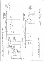
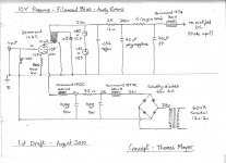
Here's a first draft - please let me know if there are any obvious mistakes! I haven't actually tried this out - my version has 280mH chokes. I'm just assuming that 60mH chokes will work in this. I have some to try out but haven't done so yet. So the voltages in the filament supply are theoretical - untested in a working model, but should be pretty close. All the iron is Hammond and very good value. The 126C OPT is really good - bifilar wound and 10K. Don't underestimate it!! It likes the 10Y too.
Filament resistor is 10 ohms wirewound and as good quality as possible. I tried several types and they all sounded different. Avoid the alu clad and the thick film. Vitreous enamel are good, but best I tried were some obsolete surplus wirewounds. A 40W part here runs at 130 degrees C. And that's above the chassis in free ambient air. So I wouldn't use anything less than 40W, and more if possible (and definitely if going in the chassis)
andy
There are three boxes in the preamp:
1) Signal chassis
2) Power Supply chassis for HT
3) Filament supply chassis
You may wish to combine one or two of these.
Here's a first draft - please let me know if there are any obvious mistakes! I haven't actually tried this out - my version has 280mH chokes. I'm just assuming that 60mH chokes will work in this. I have some to try out but haven't done so yet. So the voltages in the filament supply are theoretical - untested in a working model, but should be pretty close. All the iron is Hammond and very good value. The 126C OPT is really good - bifilar wound and 10K. Don't underestimate it!! It likes the 10Y too.
Filament resistor is 10 ohms wirewound and as good quality as possible. I tried several types and they all sounded different. Avoid the alu clad and the thick film. Vitreous enamel are good, but best I tried were some obsolete surplus wirewounds. A 40W part here runs at 130 degrees C. And that's above the chassis in free ambient air. So I wouldn't use anything less than 40W, and more if possible (and definitely if going in the chassis)
andy
Just a note about using a 26 instead of a 10Y, since this is a 26 preamp thread. Mine just morphed into a 10Y along the way because it suited the Hammond 126C. You could do a 26 version with a Lundahl LL1660/5mA instead. My rough calculation is that you could run it at 150v on the plate with a single glow tube, and 4.5mA. This would require 13.5v filament supply after the last choke and a 12 ohm cathode resistor, which could be 30W. Bias would be 12v at top of the cathode resistor.
andy
andy
Not surprising that the last Choke makes a big difference, since without it you have LOW ac-impedance between the ends of the filament. This always sounds bad, since the flow of cathode-current (through the different parts of the cathode/filament) is changed by low-Z. It 'clamps' the charge movement within the filament.
In my regulator, the choke-equivalent is the Gyrator (for the first choke) and the CCS section is the equivalent of the last choke (high ac-impedance across filament ends).
With small changes, my PCB can drive filament bias circuits in an equivalent way - so it would be very interesting to compare.
Finally, please don't assume that a 60mH choke will have the same effect as a 280mH - the ac-impedance is about 380R at 1kHz for 60mH vs. 1.8K for 280mH.
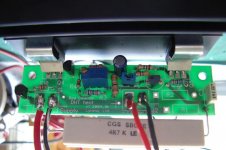
Here's a photo of the 26 (1.5V 1.05A) and 01A(5V 250mA) switchable filament driver. Just supply a raw dc of about 10V, and the board will heat 250mA filaments. Insert the PC-Motherboard Jumper link (in the centre), and the rated current rises to 1.05A for a 26. The extra large resistor soaks up the difference in voltages, instead of the transistor/heatsink - so these run cool in either mode.
In both modes, the 25-turn trimmer can accurately adjust filament current.
Special design for Cheung, these will be ready soon.
In both modes, the 25-turn trimmer can accurately adjust filament current.
Special design for Cheung, these will be ready soon.
Attachments
Hi Rod,
I should make it clear that when I chucked out the voltages regs they were simple LM1084s, not your circuit which I know from experience is much better! I haven't tried your circuit with filament bias.
Thanks for the warning about the smaller chokes. I'll try them out when I can and report back.
andy
Here's a photo of the 26 (1.5V 1.05A) and 01A(5V 250mA) switchable filament driver. Just supply a raw dc of about 10V, and the board will heat 250mA filaments. Insert the PC-Motherboard Jumper link (in the centre), and the rated current rises to 1.05A for a 26. The extra large resistor soaks up the difference in voltages, instead of the transistor/heatsink - so these run cool in either mode.
In both modes, the 25-turn trimmer can accurately adjust filament current.
Special design for Cheung, these will be ready soon.
Rod, please let me know too as these are of special interest to me too! (26/12/01 usage)
...
Here's a first draft - please let me know if there are any obvious mistakes! I haven't actually tried this out - my version has 280mH chokes. I'm just assuming that 60mH chokes will work in this. I have some to try out but haven't done so yet. So the voltages in the filament supply are theoretical - untested in a working model, but should be pretty close.... Filament resistor is 10 ohms wirewound and as good quality as possible. I tried several types and they all sounded different. Avoid the alu clad and the thick film. Vitreous enamel are good, but best I tried were some obsolete surplus wirewounds. A 40W part here runs at 130 degrees C. And that's above the chassis in free ambient air. So I wouldn't use anything less than 40W, and more if possible (and definitely if going in the chassis)
andy
Andy, if you have both left and right channel filaments fed from your 20V supply there will be anti-phase cancellation of stereo at the cathode. This widens soundstage but reduces image depth. Just thought I'd mention it
")
Attachments
Last edited:
Hi - the schematic is for one channel only in terms of the signal and the filament supply. One filament supply for each tube. I used a 60VA 12+12 toroidal wired up for 24v for each channel - two toroidals, four chokes in all. The toroidals and the first chokes are in a separate box, and the last chokes are on the signal chassis. The filament box gets its power off the PSU box so there's only one cable to the mains. Umbilicals are 4 pin XLR for filaments and 4 pin Speakon for the HT. There's only one HT supply - I should have made that clearer. Thanks for that.
andy
andy
- Home
- Amplifiers
- Tubes / Valves
- #26 pre amp