Sorry, I seem to have muddied the waters a bit.. Yes, I am strongly in favor of absolutely conventional (fixed) grid bias with the 26 and all other DHTs, and use it extensively in my own designs. IMLE, yes grid bias is superior to filament based bias and I strongly encourage you to implement.. Easiest is a a pair of 9V batteries - one for each channel will last many years..

Hi Kevin,
Thank you for your extensive reply. Your article on the 26 preamp still serves as my reference in addition to this thread. I’ll save for the Lundahls since I wanted to use them for a 10Y pre. I have a pair of Hashimoto HL 20K that are just yearning to jump into the 26 pre. I’ll get around to it one of these days.
Andy, I have to agree with Kevin and Coolzero in that battery grid bias is very good. I’m using a 133nF Russian SSG slver mica cap for the input. They are very transparent.
Coolzero, you like to try choke input on the filament supply. For me it gave a better sound and ripple is much lower with it. You may also like to put snubbing 220nF caps on either side of the choke, join them together and ground that connection. I still have a slight hum, but than may be due to the grounding in the preamp chassis itself.
Rich
The only problem is that we can´t choose battery voltage so easy as the Lithiums are 3V.
Hi,
what about a mixture of ~2*3V Lithiums as Grid bias and 2 Ohms (2Ohm *1 Ampere=2W!!!) filament bias, to reach ~ -8V Ug?
KR Hauke
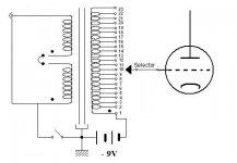
Regarding grid bias with an input transformer, normally it’s applied it to one terminal of the secondary with the other terminal going to the tube’s grid, but I’m not so sure with a TVC. Can one just apply the grid voltage as per the diagram below? Or would the variation in the resistance of secondary windings cause a problem?
Rich
Rich
Attachments
Barossi -
Great idea - combination bias. I'd forgotten about that. With 150v on the plate, this would give a little more flexibility with bias. Say 9v from a battery and 1 or 2v on the cathode. I'll have to try this!
Andy
Hi Andy,
please share your experiences then
")
KR Hauke
Hi Kevin,
Thank you for your extensive reply. Your article on the 26 preamp still serves as my reference in addition to this thread. I’ll save for the Lundahls since I wanted to use them for a 10Y pre. I have a pair of Hashimoto HL 20K that are just yearning to jump into the 26 pre. I’ll get around to it one of these days.
Andy, I have to agree with Kevin and Coolzero in that battery grid bias is very good. I’m using a 133nF Russian SSG slver mica cap for the input. They are very transparent.
Coolzero, you like to try choke input on the filament supply. For me it gave a better sound and ripple is much lower with it. You may also like to put snubbing 220nF caps on either side of the choke, join them together and ground that connection. I still have a slight hum, but than may be due to the grounding in the preamp chassis itself.
Rich
Rich, what value that the chokes you used for filament supply. I'd like to try it if I could find the required components here. Presently with the current filament supply, there is no hum (no hum at all) and the sound is exceptionally good. It is a simple LM317 voltage & current regulator together.
Thank you Andy and all for your hard work. May I suggest that the difference between filament bias and battery bias on the grid is slight compared to the improvement of replacing the potentiometer (or transformer) volume control with optocouplers.
Another option in regard to bias supply is photovoltaic cells. ie... SOLAR CELL, 60MM X 60MM X2MM | AllElectronics.com
For linestage, I ended with the 210 tube with filament bias. Perhaps I should have spent more time with the 26? I am still playing with solar cells for bias in my phono amp, but I'd like to let you know how much I am enjoying this thread!
Well, more interesting stuff. I've been using the Hammond 126C interstage which is really on the limits for a 26 - hasn't really got the inductance at 106H. I haven't got round to trying the 26 with a Lundahl LL1660, which I must do, but in the meantime I tried out the 10y with the 126C. Took me a few hours to get all the voltages right, since I'm still using a 150v glow tube rated 30mA and it's all pretty marginal, since I only have 15.5v on the filament supply voltage. After a lot of juggling I got some operating points that worked. I have 150v on the anode, 4.7v on the cathode and a 4.2 ohm cathode resistor. That should be about 12ma through the 10Y. That's about right since the 126c is rated for 15mA. Ideally I'd like some better operating points. What I have in mind is 210v on the anode, 10 ohm cathode resistor, 12mA, 12.5v on the cathode and 20v supply voltage. Not difficult at all - just have to change the filament transformer and use different glow tubes like 2 of 0C3.
Hi Rod,
You posted the FET filament supply circuit back in Nov last year, but I seem to recall that there was a resistor missing in that circuit. (pardon me if that's not the case...)
Anyway, could you post the latest circuit again? And any plan for a kit on this soon?
Actually I am also interested in using 01A sometime in the future, and in that case, what would need to be changed?
Thanks for your help!
Cheung
hello Cheung,
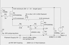
The version with enough resistors is here!
Be sure to use the FETs named, or you could need a higher supply voltage, and a bigger heatsink.
To use a different filament current, just alter R2:
R2 = 1.2/(filament current)
Yes, I'm working on the new version of the supply - today I'm trying new parts to get very low noise. I'm aiming to release a design with a big improvement in noise performance, ripple rejection, and stability, compared to the present circuit.
Attachments
Member
Joined 2006
The new circuit is very close. Most of the remaining work has to do with listening!
The new circuit will not use FETs. FETs are easier to use, but the capacitance is too high (at low voltages) to give the very best solution.
The circuit needs special Japanese Transistors to get the performance we need. I will offer those with the kit, to make it easy to build. The ordinary MJ150xx types don't work well enough when Vce gets below 5V, which is mandatory for us.
I'll probably offer it assembled too.
The target spec is to service all preamp valves and 1A filaments up to 300B with resistor changes to set up the voltage.
The same PCB with 10A transistors will aim to serve 2A3 filaments and all the way up to GM70 (20V 3A).
Stability is aimed to be better, as a control loop will set up up the filament current such that the specified filament voltage is achieved automatically. And adjustably!
Hi Rod,
You'll have a truly excellent product and you deserve to sell loads! How are you thinking of interfacing with heatsinks? These start to get big as you go from 1 amp up. Does the board fit onto the heatsink, or will the devices need to be mounted separately on heatsinks?
Andy
You'll have a truly excellent product and you deserve to sell loads! How are you thinking of interfacing with heatsinks? These start to get big as you go from 1 amp up. Does the board fit onto the heatsink, or will the devices need to be mounted separately on heatsinks?
Andy
Member
Joined 2006
Hi Rod,
You'll have a truly excellent product and you deserve to sell loads! How are you thinking of interfacing with heatsinks? These start to get big as you go from 1 amp up. Does the board fit onto the heatsink, or will the devices need to be mounted separately on heatsinks?
Andy
The heatsink is a difficult question and I'd like any input that folks here can give!
There will be two bipolar transistors in the TO-220 isolated package (no mica sheet or isolation washers needed). I intend to ship them with no heatsink, so that amp builders with a metal chassis can just attach them to the chassis surface with M3 screws. If you have a 2mm thick chassis or better, this will usually be enough. Measuring the temperature of the case can confirm this.
For the 1A filaments, here are the numbers for the thermal design:
Power dissipated in the CCS transistor is fixed at <2.5W. The transistor case can reach 120 deg C at that power (I do mean the case, not the die), so you'll need to limit the rise to 90 deg C. The little bolt on heatsinks will do fine for this:
Rapid Electronics - Electronic Components
They're rated 9 to 12 K/W [= deg C per Watt], so you could burn as much as 10W into those, at the limit. But that assumes free air circulation, so you'll need PLENTY of margin in this parameter.
The other (Gyrator transistor) burns 3.5W at the minimum supply voltage input, which is (filament voltage) plus 6V; ie 7V for the 26. if you have 9V input, the power burned is 5.5W, so some care with the dc supply is worthwhile.
So, most of the time you should be OK bolting the TO-220s to the chassis, but a small and cheap heatsink can easily supplement that.
If you have no chassis metal, a bigger sink might help:
eg Aavid Thermalloy KM100-1 gives 3.3°C/W on dimensions 45 x 30 x 100mm
Rapid 36-0210
Rapid Electronics - Electronic Components
This 3.3 K/W type can support both TO-220s together.
Make sure the amp's enclosure has vent slots for this heat, or that the heatsink sticks out the back of the amp in this case.
I'd be especially interested in hearing whether this kind of heatsinking fits in with your amps OK.
I've used Wakefield 637-20ABP on multiple designs, including 300B heating with very good, cool results. These can handle 5W dissipation under chassis with some breathing holes above for airflow. PCB mounting is very convenient and compact. Cheap, too.
They also make a 63mm high version, but it's not typically in stock. I also use a skinnier version for TO-220 rectifier and power resistor mounting.
My preference is to stay off the direct-to-chassis mounting of semi's, but to each his own.
They also make a 63mm high version, but it's not typically in stock. I also use a skinnier version for TO-220 rectifier and power resistor mounting.
My preference is to stay off the direct-to-chassis mounting of semi's, but to each his own.
More on the 10y in filament bias. Well, eventually got everything working right. Man, this is a RIDICULOUS way to build a preamp, just like Kevin says! I have a 9+9v toroid at 60VA on EACH filament supply, which gives 18v AC at 1.25A for each filament, which works out at 24vDC rectified. This goes through a LM1084 with 1.8K sense resistor to give me 20v supply voltage, so minus the 7.5v filament for the 10Y that gives 12.5V on the top of the 10 ohm cathode resistor (60W) for about 12mA. I have two VR105 glow tubes to give me 210v on the plate, into the Hammond 126C.
Having spent the whole day fixing up all this with an occasional gape at the football, I can at last listen to it. Sounds very clean and clear. Smooth and effortless too. I think this is a good result, but whether I'd build another one I don't know! But who knows - I may be happy with this one for a while. I think my next step is grid bias with a battery. Just a little bit simpler! But that will be another build. And back to the 26 again.
Andy
More on the 10y in filament bias. Well, eventually got everything working right. Man, this is a RIDICULOUS way to build a preamp
Yeah a lot of heat to burn off, but not with all tubes. Don't even need an extra resistor to bias a 3A5: Phono Preamplifier with 3a5 Directly Heated Triode
Sheldon
- Home
- Amplifiers
- Tubes / Valves
- #26 pre amp