It's easier to understand if you think of current loops, and ground (or common) reference points as independent issues.
There is a current loop for the filament. The current from the filament supply must return exactly to the filament supply.
There is a separate current loop for the current through the tube, which also must return exactly to its supply.
Let's say you are using cathode bias. In this case the current through the tube must go through the cathode resistor before it can return to the supply. And in cathode bias, the bottom of the cathode resistor is at ground (or common).
Let's take an example, of a 5V, 1amp filament, and 10mA plate current and a 1k cathode resistor.
Let's assume that the negative end of the filament is connected to the cathode resistor. With 10mA and a 1k cathode resistor, the potential at the top of the cathode resistor will be 10V. Now, the negative side of the filament will be at 10V.
If we want to use filament bias, we take the filament return voltage from the bottom of the cathode resistor, instead of from the top of the cathode resistor. Now, the filament is in series with the cathode resistor, so both the plate current and filament current must go through the cathode resistor. The total current through the cathode resistor is now 1.01R (1A+10mA). If we want the same 10V at the cathode resistor, we must calculate the new resistor size (V/I=R or R=10/1.01=9.9R).
So to get the same bias, we have reduced the cathode resistor by a factor of 100. The advantage is that we can eliminate the bypass resistor, since this low value resistor will cause very little cathode degeneration. The disadvantage is that any noise due to the filament supply ripple over the cathode resistor, will be amplified by the u of the tube.
Sheldon
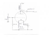
Thanks a lot Sheldon. Your explanation is an excellent education for me as usual. I put it all into a diagram; can you verify whether what I understood is correct.
Attachments
Hi Coolzero,
I am using voltage regulation not current regs for filament bias - I would otherwise use current regs, but Thomas Mayer found this didn't sound so good as a LCL filament supply. I haven't gone into the supply yet, but voltage regulation is easy to implement here just to get it up and running and get the voltages right.
Note that the 10 ohm resistor would benefit from being 11 ohm to keep the current through the 26 closer to 6mA. And a 20 watt part is really not adequate - think at least 30W or preferably 50W and that's better on top of the chassis. This resistor gets hot. On your diagram, if you have 10v on the top of the cathode resistor you have 11.5v on the other side of the filament, which is your supply voltage.
I have a 11 ohm cathode resistor (10+1 ohms, 50W and 12W vitreous enamel) and 9.7v at the top of it, so supply voltage is 11.2v.
Andy
Sheldon,
Thankyou also for the explination and Coolzero for the schematic.
Here's the link to Thomas' schematic on AA, if you haven't found it already.
Tube DIY Asylum: RE: Filament bias for DHTs - how to do it? by Thomas Mayer
Regarding filament supplies, after building a choke input one, I realised they were the way to go. I'm still using a LM350 after the LC but want to try a passive LCL when I get my hands on some 0.4H chokes
Gianluca has given some insight using a LLCCLL supply and Thomas seems to use 400 - 600mH chokes in the + leg.
Audio Asylum Thread Printer
Has anyone here tried a passive filament supply along similar lines?
Nicoch46, thanks for that interesting link, sounds like a quick weekend project .
.
Rich
Thankyou also for the explination and Coolzero for the schematic.
Here's the link to Thomas' schematic on AA, if you haven't found it already.
Tube DIY Asylum: RE: Filament bias for DHTs - how to do it? by Thomas Mayer
Regarding filament supplies, after building a choke input one, I realised they were the way to go. I'm still using a LM350 after the LC but want to try a passive LCL when I get my hands on some 0.4H chokes
Gianluca has given some insight using a LLCCLL supply and Thomas seems to use 400 - 600mH chokes in the + leg.
Audio Asylum Thread Printer
Has anyone here tried a passive filament supply along similar lines?
Nicoch46, thanks for that interesting link, sounds like a quick weekend project
. Rich
Andy/Rich,
Thanks for the information. However the Thomas Mayer’s schematic is not available it seems from that link. If someone is having it please share.
One more thing. Can someone give an idea of what values to use in this LCL filament supply to work with the mentioned voltage? I have seen one before in the same thread but not sure whether it will suit for this.
Thomas writes as follows:
"I'm using the new Lundahl filament chokes, the 2733. It has 0.1H/3,7A in parallel and 0,4H/1,7A in series connection. The filter chains themselves are LCL. The first LC section in the PSU chassis and the last L at the tubes. A small input cap can be used to tame the supply a bit, like 470uF. As cap between the chokes I use 40.000uF. I let the filament bias source end with a choke to AC decouple it from the signal path
So looks like 470uF > 400mH > 40,000mF > 400mH
I don't quite know how he adjusts the voltage here - remember he uses 801 not 26, so his filament supply is nearer 50v. "In my 801 linestage the bias resistor is only 33 Ohms. I still use the ultrapath connection. The B+ side of the lineout transformer is returned to the - side of the filament. So the AC signal actually bypasses the bias resistor (at least from the midrange on upwards)" Thomas
Andy
Hi Coolzero,
In the first link, see the end of the 3rd post by Thomas, for his filament bias.
Also just scroll down in the last link, to the schematic with the 801 driving 801. The filament chokes are 0.6H.
The Lundahl LL2733 seems to be the one developed for filament supplies. It has 2 0.2H (200mH) coils that can be used in series for 0.4H or parallel for 0.1H. From the schematic Thomas uses it in series just prior to the filament.
Just wondering about the 1st choke in an LCL supply, is it better to use 1 coil in each leg + & - (ala common mode) or use them in series just on the + leg? Can anyone share some knowledge on this?
Rich
Last edited:
Thanks a lot Sheldon. Your explanation is an excellent education for me as usual. I put it all into a diagram; can you verify whether what I understood is correct.
Yes, with the voltage correction noted by Andy.
Sheldon
Note that the 10 ohm resistor would benefit from being 11 ohm to keep the current through the 26 closer to 6mA. And a 20 watt part is really not adequate - think at least 30W or preferably 50W and that's better on top of the chassis. This resistor gets hot.
Actually, if you have a wirewound resistor rated for 10W, it is technically adequate for 10W. This is usually assumed to be in free air at 25 degrees C. Often this means it will run very hot (300 degrees C or sometimes more - see this example: http://www.irctt.com/file.aspx?product_id=69&file_type=datasheet ).
Now, you don't want to run at rated power, as that requires that everything be done just right. But note that at half the rated power, the temperature is still 200 degrees, which is fine for the resistor, but way to hot to touch.
So, the other disadvantage of this type of biasing, is that it does generate some heat, and waste some power.
Sheldon
Hi Coolzero,
Just wondering about the 1st choke in an LCL supply, is it better to use 1 coil in each leg + & - (ala common mode) or use them in series just on the + leg? Can anyone share some knowledge on this?
Rich
like Cmc I hope is better as I will use in my new phono , just try is fast
Thomas use LCL not CLC To have higth impedence?
Hi Sheldon,
As regards resistor temperatures, I bought an IR thermometer to measure this. Thorough, eh! What we do for science.....
Well, after about 15 minutes the temperature in the centre of a 10 ohm 30W vitreous enamel resistor is 150 degrees centigrade. Temperature at either end is 90 degrees. This will probably go up a bit more. Ambient temperature is 24 degrees.
Amusing little things, these IR thermometers!
Andy
Amusing little things, these IR thermometers!
Hi Andy;
IR camera is a stunning thing. You may see all your amp in colors depending on temperatures. Change layout and test again. Change heatsink and see again. Until it is near perfectly optimal!
Sheldon/ Andy,
I have 15R/50W resister in hand. If I use this with 12V supply, guess the filament will be little starved at 0.8A. Is this OK? Is it a must to have exact 1A current from the 12V supply? Which I got now is 12V-3A supply. Any other issues you could see with this setup? Appreciate your advice.
I have 15R/50W resister in hand. If I use this with 12V supply, guess the filament will be little starved at 0.8A. Is this OK? Is it a must to have exact 1A current from the 12V supply? Which I got now is 12V-3A supply. Any other issues you could see with this setup? Appreciate your advice.
Sheldon/ Andy,
I have 15R/50W resister in hand. If I use this with 12V supply, guess the filament will be little starved at 0.8A. Is this OK? Is it a must to have exact 1A current from the 12V supply? Which I got now is 12V-3A supply. Any other issues you could see with this setup? Appreciate your advice.
You are running the 26 well below its maximum current, so starving the filament by 20 percent should not be a problem. Though, I think with coated filaments, you wouldn't go much lower.
Sheldon
You need two filament supplies - one for each 26. If you mean 12V secondary that should be fine - once rectified (Schottky diodes) should give you 17v or so. Then a big cap like 15,000uF rated 25v. Three amps per supply should be OK. For testing I used a LM1085 as voltage reg. I used a 120 ohm resistor from adjust to out and a 950 ohm sense resistor from adjust to ground. Actually this was a 1.1K bypassed with a 10K pot. See data sheet for how to use the LM1085 if you do so. There are better options like chokes and better ss devices, which is my next step.
Andy
Andy
- Home
- Amplifiers
- Tubes / Valves
- #26 pre amp