Hi,
Attached schematic shows what exactly I have now.
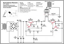
For CCS between choke and B+ supply, I used K&K audio, compact CCS (K & K Audio - Lundahl Transformers, audio DIY kits and more). Filaments are in series, fed by a SMPS used in DVD players (SMPS fo DVD SMPS - 226 SMPS for DVD CN;GUA products). SMPS works well to reduce the overall hum drastically, which I couldn't control using any other simple filament supply. Plate chokes are from EP (Electra-Print.com High-Fidelity Audio Tranformers). Most of the components I used which I had already. It is not necessary to have the exact same part mentioned. You could easily find alternatives for some of those for a lesser price.
However, to make my pre a pure DIY I am planning to replace B+ PSU with Salas simplistic regulator and Filament supply with Rod's Gyrator/CCS. Hope it will give me a better result. You could easily find the details of those in this thread if you wish to use those as well. This thread includes pretty much everything you need to build a hum free wonderful sounding 26 pre. Good luck.
Thank you so very much for taking the time compose the list for me. I will print this out and give it to my builder. Hopefully this will be a success.
I have a Broskie PS-2 power supply which is similiar but it has the Lm reg on the output after the 10m45S, so it is a series regulator. I had to go this route because I'm using a SS buffer after the tube which has a DC servo that goes nuts if the B+ voltage drifts even 100 mA which is common for shunt regulation, but this combo looks like it might hold a constant voltage?
Depends on what you mean by that. Usually a servo is used where a small DC offset will be amplified by a following stage. So it has to be very tightly regulated to a specific voltage. The servo typically references the stage output voltage, not B+. That's not an issue for a B+ supply as used here. A modest amount of thermal drift will not cause any noise on the output. As the VR tubes age, voltage may change a little. What we want is very low ripple. The type of shunt supply I posted (and the Salas supply) will hold the voltage within a volt or so, with very low ripple.
Sheldon
Cathode Caps and Resistors
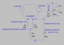
In discussing filament heating, I mentioned connecting the cathode capacitor to the negative side of the filament for best sound.
When I went to my 300BSE to mod something today, I found that I had not wired it like that in 2004. And when I tried moving the cap to the negative filament, the sound degraded badly - especially, the image was very unstable.
If you use a cathode capacitor, be sure to try it on both sides, to ensure you get best sound.
The drawing shows exactly what I use on 300Bs. The cathode resistors are split, to try to ensure that the anode current drawn from each side is the same.
C2 is the Western Electric cap, designed to improve supply rejection.
Attachments
Hi Rod,
Some advice needed here. Right now I just have a LM1084 as a current source for the 300b filaments. No gyrator. I've connected the plus to pin one and minus (off the capacitor) to pin 4. I've put the cathode resistor on pin 4. Should I put it on pin 1 which is the filament positive? I haven't used a cap yet - where do I connect that?
Best,
Andy
hello Andy,
The SE connexion sounds correct. As far as I'm aware the 300B is symmetrical (not the case for every DHT) and so either filament pin can be +ve.
If you only have one cathode resistor, connect it to the FIL -ve. Then connect the capacitor to the FIL+.
If you don't use a gyrator, try adding an HF choke in its place, to be sure rectifier current pulses and mains noise (from the filament supply) are minimized. This is especially important if your trafo is toroid.
As you've found out, the current source makes more difference than the gyrator in most cases.
With PP, depends on whether you're using a common cathode resistor, or two separates. With 2 resistors you can use 2 circuits just like SE, which I suspect is the highest quality route.
With a common cathode resistor, you CCS must be a source (not a sink), and the circuit becomes like the one I posted for PP at post 348:
http://www.diyaudio.com/forums/tubes-valves/151421-26-pre-amp-7.html#post2132441
have fun building!
Hi Rod,
As you know I'm not an EE but a humble hobbyist, and I sometimes get thrown by the theory if I'm unfamiliar with it. so I looked up current sink and source on Wiki and by the time I was knee deep in biological membranes and trolls lurking in rivers I gave up. It's a wacky read!
So am I right in thinking that a "source" is in the positive line? That's what I have - LM1084 with the input positive from the reservoir cap and output going to pin 1 which is nominally the positive pin. The negative of the cap then goes to pin 4. I'm attaching the common cathode resistor to pins 4 and 4 joined of the two 300b outputs.
I don't have room for chokes, but I'd be interested in adding a simple gyrator. I have a few LM1084 so tend to use those. Can you suggest a circuit that would add a gyrator to the LM1084 current source (or would it be sink then, if the LM1084 were in the negative side - bit hazy here?).
Andy
Andy, the quickest gyrator is just to take the ST logic level FET named in the FET version of the circuit (in this very thread).
Connect the CCS to the negative side.
Connect the V+ to the drain of the FET. connect a 1M or 1,5M resistor to V+, other end to a 1 to 5uF MKP capacitor (cap's other end to ground). Connect the RC join to FET gate via 1K resistor (carbon composition or 1206 thick-film chip). Minimise the gate wiring absolutely, or there may be subtle, or not-so-subtle oscillation trouble.
The FET source is your gyrator output.
Make sure there's 2V across the FET, and that heatsinking is adequate, before using on a filament (I use a pair of 2 Ohm 25W resistors to test them)
In discussing filament heating, I mentioned connecting the cathode capacitor to the negative side of the filament for best sound.
When I went to my 300BSE to mod something today, I found that I had not wired it like that in 2004. And when I tried moving the cap to the negative filament, the sound degraded badly - especially, the image was very unstable.
If you use a cathode capacitor, be sure to try it on both sides, to ensure you get best sound.
The drawing shows exactly what I use on 300Bs. The cathode resistors are split, to try to ensure that the anode current drawn from each side is the same.
C2 is the Western Electric cap, designed to improve supply rejection.
Hi Rod Coleman!
Do you want say about the circuit???
It is good or no??? i want try use it for my 300B Se. What is wrong in the circuit???
Attachments
")
MJE15032 measured bad in 300B circuits. Please use another, like 2SC4881.
Please check your power rating for 0.47 resistors. TO-220 thick-film 20W or 35W recommended.
9V is minimum for 300B. You can use 12V or even more, but check your heatsink rating, & test circuit on 4 Ohm resistor (2x2R 25W) to make sure transistors not too hot after 1 hour test.
Please check your power rating for 0.47 resistors. TO-220 thick-film 20W or 35W recommended.
9V is minimum for 300B. You can use 12V or even more, but check your heatsink rating, & test circuit on 4 Ohm resistor (2x2R 25W) to make sure transistors not too hot after 1 hour test.
No pardons needed. Some trial and error is good. Some engineering beforehand is even better. A current source fed shunt supply is a good combination. That what Salas's supply is. You can do it with what you have. I'd take the current source you are using before the plate choke and put in in place of R4. Increase the current so that you have about 20mA through the VR tubes. Use two OB3 tubes (will give you about 180V. Note R12 from B+ to the connection between the VR tubes on my schema. That's optional, but can help the tubes fire up). Use something less than 0.1uF cap after the VR tubes, or use a voltage divider and two small caps after the VR tubes (see the schematic I posted). Remove L2 and connect the supply to your plate choke. That should be a nice quiet supply.
If you want to try Salas's supply, just remove everything between C4 (I might use something bigger than 1uF there) and the plate choke and plug in the Salas circuit.
Sheldon
Sheldon,
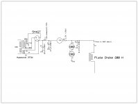
I tried this and below is what I have ended up with. This gave the best sound overall and quieter B+. Overall sound of the pre improved noticeably and now there is much more resolution and control to the bass and treble. Thanks a lot, it worth the change.
Attachments
Last edited:
Looks nice and simple. You can probably remove R4 also. If the current source is a robust design and can dissipate the heat from the voltage drop, the resistor isn't necessary. You show B+ at the plate choke at 260V. Are you sure that's correct? I'd expect something around 180V (two 90V VR tubes in series).
Sheldon
Checked out the KandK current sources, and your transformer. Looks like you are dropping around 200V. So, on second thought, unless you have a hefty heat sink, I might leave the resistor there to dissipate some of the heat. Not sure of the size though. How much current through the tube? Does this supply one tube or two channels? I'm curious on Rod's take. Would a dropping resistor be better before or after the CCS?
Sheldon
Sheldon
Checked out the KandK current sources, and your transformer. Looks like you are dropping around 200V. So, on second thought, unless you have a hefty heat sink, I might leave the resistor there to dissipate some of the heat. Not sure of the size though. How much current through the tube? Does this supply one tube or two channels? I'm curious on Rod's take. Would a dropping resistor be better before or after the CCS?
Sheldon
Last edited:
That what Salas's supply is. You can do it with what you have.
Sheldon
Not exactly. There is no gain error loop active regulation in this approach. Performance isn't on par. Although nice and very ''tube''.
Not exactly. There is no gain error loop active regulation in this approach. Performance isn't on par. Although nice and very ''tube''.
Didn't mean to imply complete equivalence - just that both are shunt supplies fed by a current source. No question, your shunt regulator is much more sophisticated, and more tightly regulated, with lower Zout. Better "performance"? Certainly, in technical terms. Sounds better in this circuit? I guess it would have to be tried. It won't look as cool, though.
Sheldon
Has been tried by the now elusive DISCO. Remote sensing would be very easy to have and battle the needed long wires too if there is a gain loop.
http://www.diyaudio.com/forums/tubes-valves/151421-26-pre-amp-27.html#post2009918
http://www.diyaudio.com/forums/tubes-valves/151421-26-pre-amp-27.html#post2009918
This circuit Supply for PRe, the sound is bad,
The Simpler Simplistic Design by Salas kill it.
EX; I have been to many the design supply for PRE, but i don't like them.
I think: The Simpler Simplistic Design by Salas:
Advantages: simple design, easily made, low cost, improved sound clarity.
Cons: must use a large heat sink
The Simpler Simplistic Design by Salas kill it.
EX; I have been to many the design supply for PRE, but i don't like them.
I think: The Simpler Simplistic Design by Salas:
Advantages: simple design, easily made, low cost, improved sound clarity.
Cons: must use a large heat sink
What is bad? A CCS and a couple of OB3s? Naahh. Sounds silky. Its just lacks resolution and impact but not bad. Have you used that circuit, CCS and tube ''zeners'' exactly?
This is not good. I think OD3 for shunt, the sound is not good!
Attachments

Looks nice and simple. You can probably remove R4 also. If the current source is a robust design and can dissipate the heat from the voltage drop, the resistor isn't necessary. You show B+ at the plate choke at 260V. Are you sure that's correct? I'd expect something around 180V (two 90V VR tubes in series).
Sheldon
Checked out the KandK current sources, and your transformer. Looks like you are dropping around 200V. So, on second thought, unless you have a hefty heat sink, I might leave the resistor there to dissipate some of the heat. Not sure of the size though. How much current through the tube? Does this supply one tube or two channels? I'm curious on Rod's take. Would a dropping resistor be better before or after the CCS?
Sheldon
Your guess is right. I tried it without the dropping resistor but CCS couldn't handle the flow. This way it works. As long as I keep the dropping resistor in place, nothing much of heat generated in CCS. Tested it for couple of hours and it was quite OK with running both the channels together. Current through the tube is close to 6ma. CCS is with a 3W heat sink btw. If my memory is correct, K&K's suggestion was to use the CCS after the VR's initially. I tried both the ways and felt there is slightly more resolution to the sound with latter. What do you think?
Sorry, it was a mistake mentioning both VR tube as OB3. Actually the first tube I am using is an OA2. Voltage is around 240 volts on plate chokes.
Attachments

Last edited:
- Home
- Amplifiers
- Tubes / Valves
- #26 pre amp