Boy, after struggling with this same issue (and eventually resorting to standard LT1086 CCS heating), I really have my doubts that any BJT on the planet can accomplish this.
I recall my power electronics pseudo-professor (he was actually a design engineer in the real world) saying he always designs his BJT circuits assuming a beta of 10. Period, no exceptions. After much frustration, I am starting to agree with this formula. Especially when low capacitance is an important performance parameter.
That would be one heckuva transistor to accomplish this at even poor capacitance performance.
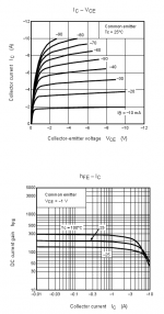
Forced beta of 10 is right for any circuit requiring saturation, or any circuit using old design BJTs. I had not appreciated how far behind the MJE15032 was compared to the Japanese, like the ROHM 2SC5511 I made my original heater with.
Since ROHM have withdrawn that one, we must turn to TOSHIBA. They have NPNs and PNPs with hugely improved performance, backed up by a specification that covers our area of interest. For PNP, just look at the 2SA1887 specs: over 5A for 40mA base current at 2V, specified.
In the circuit example, I show more like 80mA base current.
Attachments
Hi Rod:
Thanks aaaahh lot ! I hope very soon I can finally start listening to some music after 2 years of building my PPP amp. The 26 preamp later on should be the "crown" !
Forgive me to ask this silly question, but I don't understand why there is only 1 drum cored choke L1 ? What should be the spec of the choke ?
Once again, thanks for your help.
Regards,
NG
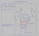
NG, how many cathode resistors do you have? If there is only one shared, then one choke must be used. If PUSH and PULL have their own resistor,use 2x 6A chokes.
For 10A, Try the EPCOS B82725J2103N022 double toroidal ferrite choke. Wire the + and the -ve through it. This does a great job of sucking out HF noise.
EPCOS|B82725J2103N022|CHOKE, RING CORE, DOUBLE, 1.8MH | Farnell United Kingdom
Both chokes together drop 0,26V at 10A, so be sure you still have 5,0 .. 5,5V remaining at the CCS under full load.
Rod , do you know if your Gyrator+CCS has been tried with high sensitivity headphones (SPL lmV =100dB), I know the newer low current Tent labs module has been tried and had no hum. These #26 Preamp discoveries naturally lead to a headphone implementation.
I had lot of questions about the circuit, mostly for preamp or 300B/2A3 duty. Nobody mentioned headphones. But having heard good reports in this thread about applications using the 26, as well as 300B power amps, I would expect it to work very well.
Where hum is the most important measure, be sure to have enough Vce across each transistor, to keep the Hfe high and capacitance low. 2 to 5V is the working range dependant on your heatsink size and transistor choice.
NG, Connect the cathode resistor (& cap if used) to the negative filament terminal on the valve base. Connect the other end of the resistor to HT 0V (Ground).
When you buy parts for the 2A3 build, get some 1 ohm 15..25W resistors to test it. build and adjust the current sense resistor till the 2A3 filament has 2.4..2.5V across it (no more!). Then, leave it for some hours on test, keep checking the voltage, and make sure the transistors don't get too hot. That way, you can be sure your heatsink is big enough.
Burning out your filaments because of a mistake in the circuit would be no fun!
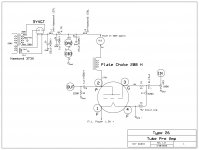
Finally I have completed the pre-amp. Attached the schematic (sort of Kevin Kennedy, Jim D'Cort mixture). Thankful to Kevin for his great advices to come up with this final circuit which work nicely and worth all the efforts. Used a PSU with Hammond 372 X (which I had already otherwise an overkill I suppose) +5U4GB+10K(5W)+OA2/OB3 tube regulators+IXCY CCS (kit module K&K Audio -http://www.kandkaudio.com/accessories.html) to produce 250V hum free B+ which I built out of randomly picked up items I had already. Otherwise, any simple PS schematic would work I assume. For me, use of regulated B+ helped towards reducing the hum drastically. Hum with unregulated B+ was unacceptable to me (even though it sound great). For filament, I used a cheap China made external DVD SMPS which worked greatly with no hum at all.
Attached a picture of the final product (pardon for my poor craftsmanship).
Coolzero,
I don't have technical skill to build the 26 preamp that you've mentioned here but i am thinking about commision it to someone who knows how. What do i need to provide him other than the schematics that you've listed here (is this the final version by the way.) Do you have a parts list required to build this preamp. Also can you give some tips and tricks on how to eliminate the hum that i've heard so much associated with the 26 preamp. I really appreciate any help that you can provide. Thanks.
xecluded
Hi Rod,
Which one results in better sound quality? Does it differ between preamp and power output tubes?
I haven't done any direct comparisons, sadly. But the different circuits I built did not vary much in sound, so far I can tell. However, the difference between ac, dc (just rectified) and ANY of the circuits is very noticeable.
Best plan is to build according to the parts you can easily get. But if you choose FETs, be sure they are logic-level types with a low Vgs (th) turn-ON voltage - About 1,7V for preference. Allow 2,5V across these types.
If you can get Japanese BJTs on the list above, these may work down to 1,5V across each, but 2 to 2,5V is better for low capacitance.
If you can only get the MJ150xx series BJTs, I would probably build with FETs, since these seem to have poor performance at low Vce.
Coolzero,
I don't have technical skill to build the 26 preamp that you've mentioned here but i am thinking about commision it to someone who knows how. What do i need to provide him other than the schematics that you've listed here (is this the final version by the way.) Do you have a parts list required to build this preamp. Also can you give some tips and tricks on how to eliminate the hum that i've heard so much associated with the 26 preamp. I really appreciate any help that you can provide. Thanks.
xecluded
Hi,
Attached schematic shows what exactly I have now.
For CCS between choke and B+ supply, I used K&K audio, compact CCS (K & K Audio - Lundahl Transformers, audio DIY kits and more). Filaments are in series, fed by a SMPS used in DVD players (SMPS fo DVD SMPS - 226 SMPS for DVD CN;GUA products). SMPS works well to reduce the overall hum drastically, which I couldn't control using any other simple filament supply. Plate chokes are from EP (Electra-Print.com High-Fidelity Audio Tranformers). Most of the components I used which I had already. It is not necessary to have the exact same part mentioned. You could easily find alternatives for some of those for a lesser price.
However, to make my pre a pure DIY I am planning to replace B+ PSU with Salas simplistic regulator and Filament supply with Rod's Gyrator/CCS. Hope it will give me a better result. You could easily find the details of those in this thread if you wish to use those as well. This thread includes pretty much everything you need to build a hum free wonderful sounding 26 pre. Good luck.
Attachments
Last edited:
I don't understand your B+ supply. You take a perfectly good shunt regulator and follow it with a choke and CCS, then a plate choke. I can't believe that the choke and CCS are necessary for good noise performance. If so, there is something wrong. Normally, the OD tubes are followed by a small (less than 0.1uF) cap. A large cap can cause oscillations. The following choke complicates the picture further. Have you tried it without the choke and CCS, and with a proper small cap?
Sheldon
Sheldon
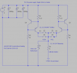
Here's an example of a little overkill: The Miada regulator before the current source offers some ripple reduction to the current source. However, the primary reason I put it there was to offer high voltage protection to the current chip, in event of a no load condition (OD tubes disconnected and ps disconnected from amp). This supply powers a phono amp that has a cascode input, with essentially zero PSRR. Note that the zener symbols at the output represent OD2 tubes. There is no filtering after them and the amp is quiet.
Sheldon
Sheldon
Attachments
I don't understand your B+ supply. You take a perfectly good shunt regulator and follow it with a choke and CCS, then a plate choke. I can't believe that the choke and CCS are necessary for good noise performance. If so, there is something wrong. Normally, the OD tubes are followed by a small (less than 0.1uF) cap. A large cap can cause oscillations. The following choke complicates the picture further. Have you tried it without the choke and CCS, and with a proper small cap?
Sheldon
Sheldon, pardon my amateurs know how in this subject. What I did was just a trial and error. For some reason it worked. I would definitely try your suggestion and let you know how it goes. Thanks a lot.
Here's an example of a little overkill: The Miada regulator before the current source offers some ripple reduction to the current source. However, the primary reason I put it there was to offer high voltage protection to the current chip, in event of a no load condition (OD tubes disconnected and ps disconnected from amp). This supply powers a phono amp that has a cascode input, with essentially zero PSRR. Note that the zener symbols at the output represent OD2 tubes. There is no filtering after them and the amp is quiet.
Sheldon
Still slowly learning about all these
 . Your schematic and explanation cleared some of the doubts I had. Thanks again.
Sheldon, pardon my amateurs know how in this subject. What I did was just a trial and error. For some reason it worked. I would definitely try your suggestion and let you know how it goes. Thanks a lot.
No pardons needed. Some trial and error is good. Some engineering beforehand is even better. A current source fed shunt supply is a good combination. That what Salas's supply is. You can do it with what you have. I'd take the current source you are using before the plate choke and put in in place of R4. Increase the current so that you have about 20mA through the VR tubes. Use two OB3 tubes (will give you about 180V. Note R12 from B+ to the connection between the VR tubes on my schema. That's optional, but can help the tubes fire up). Use something less than 0.1uF cap after the VR tubes, or use a voltage divider and two small caps after the VR tubes (see the schematic I posted). Remove L2 and connect the supply to your plate choke. That should be a nice quiet supply.
If you want to try Salas's supply, just remove everything between C4 (I might use something bigger than 1uF there) and the plate choke and plug in the Salas circuit.
Sheldon
Last edited:
No pardons needed. Some trial and error is good. Some engineering beforehand is even better. A current source fed shunt supply is a good combination. That what Salas's supply is. You can do it with what you have. I'd take the current source you are using before the plate choke and put in in place of R4. Increase the current so that you have about 20mA through the VR tubes. Use two OB3 tubes (will give you about 180V. Note R12 from B+ to the connection between the VR tubes on my schema. That's optional, but can help the tubes fire up). Use something less than 0.1uF cap after the VR tubes, or use a voltage divider and two small caps after the VR tubes (see the schematic I posted). Remove L2 and connect the supply to your plate choke. That should be a nice quiet supply.
If you want to try Salas's supply, just remove everything between C4 (I might use something bigger than 1uF there) and the plate choke and plug in the Salas circuit.
Sheldon
Thanks Sheldon for the advice. I'll try this out soon.
Kanishka
Here's an example of a little overkill: The Miada regulator before the current source offers some ripple reduction to the current source. However, the primary reason I put it there was to offer high voltage protection to the current chip, in event of a no load condition (OD tubes disconnected and ps disconnected from amp). This supply powers a phono amp that has a cascode input, with essentially zero PSRR. Note that the zener symbols at the output represent OD2 tubes. There is no filtering after them and the amp is quiet.
Sheldon
I have a Broskie PS-2 power supply which is similiar but it has the Lm reg on the output after the 10m45S, so it is a series regulator. I had to go this route because I'm using a SS buffer after the tube which has a DC servo that goes nuts if the B+ voltage drifts even 100 mA which is common for shunt regulation, but this combo looks like it might hold a constant voltage?
- Home
- Amplifiers
- Tubes / Valves
- #26 pre amp