This is killing me. I have an AC heated 46-PP driving a 300B-PP with about 500uV of 120Hz hum, and I'm ready to rebuild the whole works with these current sources.
Enough already !
Do it man ! I mean rebuild it with the CCS

Edit: On second thought 500uV of 120Hz ripple on the output is actually a pretty good result. I have simple CCS's in my SE amplifier and I have just about that much 120Hz ripple on my outputs - even with 100dB efficient speaker system (-3dB @ 30Hz) it is not audible. So are you pulling our legs?
Last edited:
No, those are true numbers, and yes, the hum is inaudible with 92 dB speakers until I'm about 3 inches away from the woofer. No complaints from that end.
This is more of an issue of having a setup that no longer requires nulling, and eliminates the major source of IM distortion in the amp. (how much IM do I have, no idea).
Rod's design is just so simple yet effective, it's hard to "just say no".
This is more of an issue of having a setup that no longer requires nulling, and eliminates the major source of IM distortion in the amp. (how much IM do I have, no idea).
Rod's design is just so simple yet effective, it's hard to "just say no".
No, those are true numbers, and yes, the hum is inaudible with 92 dB speakers until I'm about 3 inches away from the woofer. No complaints from that end.
This is more of an issue of having a setup that no longer requires nulling, and eliminates the major source of IM distortion in the amp. (how much IM do I have, no idea).
Rod's design is just so simple yet effective, it's hard to "just say no".
I agree, particularly with the comments about nulling and IM, this is the problem I have with my PP 300B amplifiers - ccs based dc filament supplies would just kill those sorts of issues stone dead. I would say on that basis it would be very worthwhile if you have sufficient space.
I do have a cathode bias cap though - this old schematic shows it on the +ve side, but I think I found the -ve side sounds better.
Rod,
Have you compared your "Y-solution" with using a single cathode resistor connected to the same ve-side as the cap?
Rod,
Have you compared your "Y-solution" with using a single cathode resistor connected to the same ve-side as the cap?
Lars, not done that yet - on the 300B. I am overdue to replace that Cerafine cathode cap with an MKP, so when that happens, I could test it.
On the LP2, operated at 100V/8mA, two resistors to ground sounded best. The best sound had to be found by experiment.
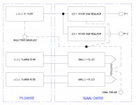
Sorry to keep resurrecting this thread with basic questions but I am sooooo close to building my 26 pre and I really want to get it right the first time. The latest noob question is about grounding and parts location. The block diagram attached shows the grounding scheme and circuit block locations I am planning on using and hopefully it is understandable. Basically there are six wires running from the PS to signal chassis with the regulators on the signal chassis and the transformers and filters on the ps chassis. I’m particularly worried about the grounding scheme because I only have a 50% success rate getting remote supplies quiet. I gave up on it for years in fact until I built an idht transformer coupled pre last year. That one worked but I had no B+ regulators, otherwise the layout was similar. So, can anyone see obvious problems with this or offer any advice for improving the layout?
Thanks again,
Marty
Thanks again,
Marty
Attachments
Sorry to keep resurrecting this thread with basic questions but I am sooooo close to building my 26 pre and I really want to get it right the first time. The latest noob question is about grounding and parts location. The block diagram attached shows the grounding scheme and circuit block locations I am planning on using and hopefully it is understandable. Basically there are six wires running from the PS to signal chassis with the regulators on the signal chassis and the transformers and filters on the ps chassis. I’m particularly worried about the grounding scheme because I only have a 50% success rate getting remote supplies quiet. I gave up on it for years in fact until I built an idht transformer coupled pre last year. That one worked but I had no B+ regulators, otherwise the layout was similar. So, can anyone see obvious problems with this or offer any advice for improving the layout?
Thanks again,
Marty
It goes without saying that the signal and power ground meccas must be connected together via the umbilical, and there should only be one connection between the two.
One point in each chassis becomes the point where all grounds are connected together - those, and only those gnd points are connected together between the chassis.
Do not allow filament currents to flow through the ground path in the umbilical - they must return through their own return lead. No filament current should flow into any ground whether in the supply or audio chassis - so they should be grounded only in one place. (In my case usually the PSU except in the case of dhts where I ground in the audio chassis as there is audio current present in that case. )
In the case of full wave rectification the center tap should go to the negative terminal (or as appropriate for the supply polarity) of the first filter cap and from there to the common grounding point (star ground) or grounded end of ground bus if you are using a bus. Same basic rule applies for bridges as well, except obviously it is one of the outputs of the bridge rather than the CT. This serves to keep the high ripple currents out of the ground path, and generally results in somewhat less ripple on the output of that first cap as well.
Here's some numbers from my latest attempt to get all the voltages right.
PSU HT = 365vDC
Dropper resistor to glow tubes - 3.2K, 9W
Glow tubes - 150v and 105v total 255v
IXYS cascode active load - sense resistor 470R
Anode voltage 178v
Cathode voltage 11.2v
Current 6mA
Cathode resistor 1.85K (2.4K // with 8.2K) wirewound
Seems to sound pretty good - full and detailed.
andy
Instead of a dropper resistor, why not use a ccs ? This will provide virtually infinite source resistance plus greatly enhanced psu rejection.
Would this be needed as well as the IXYS cascode? If so any designs you have in mind?
andy
Well not needed. But try it.Would this be needed as well as the IXYS cascode? If so any designs you have in mind?
CCS -> glow tubes = good shunt reg psu.
The CCS before the glow tubes should be IXYS cascode as well. But should be set for the circuit current draw plus 10-20mA extra for the glow tubes to shunt.
Last edited:
The CCS before the glow tubes should be IXYS cascode as well.
Now that's overkill.
Sheldon
An IXYS cascode feeding the glow tubes is nice, however the max current one can dial in is less than when using single device.
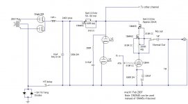
I was forced to use use a single device in my 12B4 linestage (attached). From memory I think around 45-50 mA is tops for a cascode.
I was forced to use use a single device in my 12B4 linestage (attached). From memory I think around 45-50 mA is tops for a cascode.
Attachments
True, the IXYS part in cascode has a limited current range. You can get a little more with the DN2540. I use them at 65 mA with no problems, and have gone as high as 75.
I really like the CCS-gas tube method. Three out my four tube stages use it with excellent results. Reliable firing, ultra low ripple let through, and quite compact mounting. 4W dissipation is no problem at all with the right heatsink. And that beautiful purple, pink, or orange glow....
I really like the CCS-gas tube method. Three out my four tube stages use it with excellent results. Reliable firing, ultra low ripple let through, and quite compact mounting. 4W dissipation is no problem at all with the right heatsink. And that beautiful purple, pink, or orange glow....
mach1
In the 12B4 schematic you are posting above, it seems like you are using one single pair of OC3 for both channels. I posted a question regarding a setup like this in one of the 12B4 threads some time back, and was told that I would probably need a pair for each channel. I never understood the logic behind this since the current is not passing through the VR tubes. Please, share your thoughts regarding this.
In the 12B4 schematic you are posting above, it seems like you are using one single pair of OC3 for both channels. I posted a question regarding a setup like this in one of the 12B4 threads some time back, and was told that I would probably need a pair for each channel. I never understood the logic behind this since the current is not passing through the VR tubes. Please, share your thoughts regarding this.

point is that current must pass through VR tubes ; or you can leave them in drawer
just imagine them as super duper big zenners , maybe you'll dig their role that way
Yes, but only approx 22mA (5ma+40ma/2), and NOT the current that passes through the 12B4 tubes, right? If so, the VR tubes would be out of limit at 62mA (22mA + 20mA for each of the 12B4 tubes).
OK - so I missundertood your post
so - just to "complete" what you are saying .....
in any case - best praxis is when shunt chain ( be it gass tubes , or sand ) is drawing at least same current as load ( in this case 12B4) .
ages ago I "developed" ( same as reinventing the wheel) VR stabilization in 12B4 thread , with plain resistor as series element in reg ; boyz just refused anything more complicated
VR tubes were biased in mid of their operatuing current range , and that's just enough for one channel of 12B4 .
I saw several times shunt regs with shunt element underbiased for their role - not underbiased looking at their own operating range , but comparing to load current . that's exactly the case in schematic posted above .
beat me if I know what's logic behind that ...... even added shunt resistor in parallel to load/VR combo will strighten things , considering that regulation tasks for constant current load aren't that much critical
bequerel,
In the 12B4 schematic, 18 - 20mA is shunted down the glow tubes. This safely allows for one 12B4 to be pulled or fail without glow tube failure. If two tubes are pulled or fail simultaneously, then the glow tubes will be operating outside their max range of operation and will probably fail. If this scenario bothers you, then use a separate shunt for each channel.
A shunt reg only needs to be able to vary its current conductance over the range which the load fluctuates: its effectiveness depends on its ability to respond to change in source or the load.
If the shunt current is large with respect to the load current, then any change in the load current requires a proportionally smaller change in the shunt current, thus increasing its effectiveness (given equal shunt transconductance). Taking this situation to extremes, shunting 1000 times the load current through an entirely passive device (a resistor) can achieve an efficiency equivalent to a shunt based on an active device. However, one must remember that the effective transconductance of the glow tubes changes over their range of operation (from memory it peaks at around 14mA for a 0C3), and is reduced at higher currents. In this instance, the loss of transconductance resulting from biasing the glow tubes higher effectively swamps the proportionality gains referred to above, and also renders the glow tubes liable to failure should one linestage channel fail.
The answer: If you really need better shunt operation, use a separate set of glow tubes for each channel, and run around 14 - 20mA through each string. I didn’t have the space to do this, and seriously doubt the cost/complexity effectiveness, given that the glow tubes are being fed by and feeding highly stable constant current sources. If the current load was one which varied significantly over its operational range – eg class AB push pull or even regulating screen voltages, then extra shunt complexity would be warranted.
- Home
- Amplifiers
- Tubes / Valves
- #26 pre amp