Kevin,
DHT models: Composite Tube Models
I have also made a 6B4G model from the included 2A3.
Made the "triodeh.sym" myself in LTSpice. Can mail it if you need it.
The "gyrator" can of course be cascoded using two FETs.
DHT models: Composite Tube Models
I have also made a 6B4G model from the included 2A3.
Made the "triodeh.sym" myself in LTSpice. Can mail it if you need it.
The "gyrator" can of course be cascoded using two FETs.
Last edited:
Member
Joined 2006
Hi Lars,
Does LL1676 fit 26 tube nicely? It doesn't seem to have high enough inductance at the primary, does it?
No, probaly too small as you say. Better suited with tubes as eg. 12B4 and 6n6p.
It doesn't seem to have high enough inductance at the primary
Where did you get that info? I talked to Per Lundahl a while ago and he was reluctant to give any specific figures.
My guess is you can count on at least 200H. Can measure mine if this is of major interest. Compare it to its smaller brother 1544A that is said to be 80k. The 1676 has enough core to give 5,5V out in 4:1.
Member
Joined 2006
Where did you get that info? I talked to Per Lundahl a while ago and he was reluctant to give any specific figures.
My guess is you can count on at least 200H. Can measure mine if this is of major interest. Compare it to its smaller brother 1544A that is said to be 80k. The 1676 has enough core to give 5,5V out in 4:1.
A sheer guess

Will be interested to know your measurement, actually interested in them as well

Hi Guys,
I’m stoked that my 26 preamp works. I just finished wiring up one channel for testing, it sounds great and I’m surprised that there is not much hum at all, but microphonics is another matter. This is my second scratch built valve project, the first being a 6N2P lampizator for my CD player. I must admit I thought I was being a hero trying the 26 without much experience, but all the info and excellent advice offered on this site as well as Kevin’s write up on his 26 pre helped with proper planning and building. So a big thank you for all the advice and to Andy for raving about DHT’s in preamps almost everywhere on the net. I simply had to build one.
I’m using the 2 Hammond 150H chokes as plate loads and a 0.22uF output cap similar to Gary Pimm’s 26 pre. I’ve built the prototype on a wooden chassis that also will allow me to try that Hashimoto transformer later. It’s a 3 chassis preamp at the moment, power supply, filament supply and preamp.
Filament supply is 6V XF 1N5822 diodes – 16000uF – 1R – 16000uF – Lm1086 ccs.
I’ll post some pictures later.
Rich out
45 & Kevin,
Thank you for the advice on transformer loading and other options, I’ll experiment with step-ups in my setup first.
Just one quick query, should I load the secondary of the 20K:600 XF with a 600 ohm resistor or just leave it open?
Cheers,
Rich
I would leave it open if you get a smooth high frequency response.
In this case the load will be the input impedance of your power amp. If you have a typical 47K (+ some pF's that matter for high frequencies) the low frequency cut-off should be well below 20Hz anyway.
The 600 ohm resistor (or other values) would serve as equalizer if you don't get a smooth high frequency response. Also distortion could change substantially with or without additional load resistor.
However off-band peaking could not not be a problem. It would be a problem with feedback.....
Try different solutions, listen to them and choose what you like!
Cheers,
45
Last edited:
Latest update on my 26 pre. Replaced the plate resistors with 200H custom built plate chokes by Jack Elliano@Electra Print. Worth every penny. Greatly improved the sound stage as well as it gave more authoritative and precise top to bottom. Thanking to Jack for his quality piece of work. 
45,
Thanks once again, I'll give transformers a shot hopefully this weekend.
Fingerx,
I'm using a 1.2 ohm 5W wire wound. Just divide V ref by the current of the filament. 1.25V/1.05A = 1.2 ohms.
I thought I might have to use the Ronan regulator, but the CRC filter with big caps works fine.
Cheers,
Rich
Thanks once again, I'll give transformers a shot hopefully this weekend.
Fingerx,
I'm using a 1.2 ohm 5W wire wound. Just divide V ref by the current of the filament. 1.25V/1.05A = 1.2 ohms.
I thought I might have to use the Ronan regulator, but the CRC filter with big caps works fine.
Cheers,
Rich
Member
Joined 2006
I remember somewhere I read that someone combined a + and a - filament voltage regulators and yielded tiny hum. Could this because the signal path was somewhat isolated from the power supply?
So another thought here...how about in the filament regulator, one puts a 1083 current source, the filament and another 1083 current source in series, would that creat any enhancement to hum isolation from ps?
Thanks for your comment!
So another thought here...how about in the filament regulator, one puts a 1083 current source, the filament and another 1083 current source in series, would that creat any enhancement to hum isolation from ps?
Thanks for your comment!
Use a gyrator in the +ve path, and a transistor current source in the negative path.
This really knocks out the hum, and gives wonderful sound, too.
schematic:
http://www.diyaudio.com/forums/tubes-valves/38248-new-dht-heater.html#post446973
Adding the isolating transformer is very effective against mains noise.
This really knocks out the hum, and gives wonderful sound, too.
schematic:
http://www.diyaudio.com/forums/tubes-valves/38248-new-dht-heater.html#post446973
Adding the isolating transformer is very effective against mains noise.
Member
Joined 2006
Great Rod, so that nice circuit orginated from you!
I gathered at the end of that post, Thorsten suggested something like using the LT1085/1033 pair.
Could anyone come up with that circuit? Would it simply be that just using 1085 ccs in the + path to filament while 1033 ccs put in place at the - path? So a current source and a current sink is born?
I gathered at the end of that post, Thorsten suggested something like using the LT1085/1033 pair.
Could anyone come up with that circuit? Would it simply be that just using 1085 ccs in the + path to filament while 1033 ccs put in place at the - path? So a current source and a current sink is born?
Great Rod, so that nice circuit orginated from you!
I gathered at the end of that post, Thorsten suggested something like using the LT1085/1033 pair.
Could anyone come up with that circuit? Would it simply be that just using 1085 ccs in the + path to filament while 1033 ccs put in place at the - path? So a current source and a current sink is born?
Sadly, that would give very different performance. I believe Thorsten was thinking out loud there!
One reason the current source filament drive sounds good is that the dynamic impedance (presented to the filament) is high. Adding a voltage regulating loop results in LOW dynamic impedance, and the sound is degraded.
If you are concerned with ease of build, you could use the LT108x as current sink (negative end) but try to build the gyrator - it's easy to do, with no stability troubles.
Alternatively, could even use a FET for a single transistor gyrator solution. In that case, use 1M gate supply resistor, 470nF capacitor, 1K gate resistor stopper (right at the gate pin).
Great Rod, so that nice circuit orginated from you!
I gathered at the end of that post, Thorsten suggested something like using the LT1085/1033 pair.
Could anyone come up with that circuit? Would it simply be that just using 1085 ccs in the + path to filament while 1033 ccs put in place at the - path? So a current source and a current sink is born?
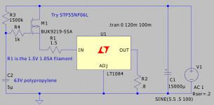
Cheung, try this for FET-gyrator version. Just make sure to us a FET with high power handling, and low threshold [Vgs(th)]. STP55NF06L seems a good low cost starting point.
I prefer the bipolar transistor current source, but for folks that like the chips, here's the LT1084 in this case. You might get away with 5.1V - but 5,5V supply would probably be better. The FETs have higher overhead than bipolar transistors (and so will get hotter, too). Take care to bolt the FET to some big piece of chassis!
Attachments
- Home
- Amplifiers
- Tubes / Valves
- #26 pre amp