anufacturer Zetex (Diodes inc) ZTX868 is probably nearest equivalent.
Well if the 1051 does not need heatsinking..I guess it won't be a problem soldering it...since it is quite a big part I suppose.
Andy, I think the umbilical idea is perfect.
Have you tried locating the caps right up close to the transformer? I try to keep the wiring between the rectifier and caps (and the trafo) as short as possible, because the CURRENT running along those wires is a pulse train of 2 to 5A peak, with fast rise time and high-band recovery pulses (even with schottkys!). With long wires there is a risk of electromagnetic coupling into the amp.
I've started to put the reservoir cap for the filaments in the PSU box. Well actually I split it - 10,000uF in the PSU box and 10,000uf in the signal chassis. How about that?
andy
I've started to put the reservoir cap for the filaments in the PSU box. Well actually I split it - 10,000uF in the PSU box and 10,000uf in the signal chassis. How about that?
andy
It'll make a difference for sure. Especially with a little bit of choke (ferrite will be fine, 1mH or more, 5A rated at least, to cover the peak current) on the output of the trafo box.
Then, to ride first class, use a feedthrough capacitor on the wall on the box to run the +ve through. Wire the box to the rectifier/cap neg using thick braid.
Hi All,
Rod, you’re a wealth of knowledge, thank you once again for taking the time to design a heater supply for us. I’ve already ordered the parts for this psu. Yay!
Andy, I’m doing something similar but I though about adding a pre-regulator, i.e. transformer – diodes 160000uf Lm7809, all in the filament psu box. But I’ll go with Rod’s suggestion.
Rod, is this circuit attached below correct? Does it need to be a metal box or is wood ok?
Also regarding your final all fet heater regulator, how close does it have to be to the valve, is 17cm too far?
Cheers,
Rich
Rod, you’re a wealth of knowledge, thank you once again for taking the time to design a heater supply for us. I’ve already ordered the parts for this psu. Yay!
I've started to put the reservoir cap for the filaments in the PSU box. Well actually I split it - 10,000uF in the PSU box and 10,000uf in the signal chassis. How about that?
Andy, I’m doing something similar but I though about adding a pre-regulator, i.e. transformer – diodes 160000uf Lm7809, all in the filament psu box. But I’ll go with Rod’s suggestion.
Rod, is this circuit attached below correct? Does it need to be a metal box or is wood ok?
Also regarding your final all fet heater regulator, how close does it have to be to the valve, is 17cm too far?
Cheers,
Rich
Attachments
Rich, the feedthrough cap looks like this:
Rapid Electronics - Electronic Components
I think Farnell have these too.
The two leads are B+ in and B+ OUT. The body and nut form the other terminal of the cap.
Feedthough caps only make sense if you have a metal enclosure that you are trying to keep electromagnetic pollution contained within. The enclosure can be partly meshed, to allow ventilation of your trafo. Use braid to wire the cap -ve to the enclosure. you don't need the braid all up to the preamp itself.
If you use a CCS and a gyrator (I think I'd use the FET gyrator now) and have enough headroom, the 7809 will not help much (unless you have mains that varies by 20% or something!).
I find regulators of this kind terribly noisy, and that won't help!
Hi Rod,
I have gone with a wooden chassis as my metal working skills are poor and I lack the tools. But will add some metal mesh for looks")
Is there a preferred value for this feed through cap? I suppose a ceramic cap will do. I’ve had good experience with those Russian PETP caps and there is a whole thread here on them. Is one limited with cap choice?
http://www.diyaudio.com/forums/parts/143675-petp-capacitors-one-best.html
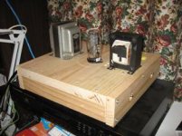
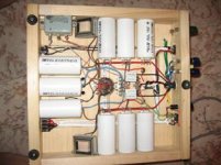
Here is a pic of my high voltage psu.
Rich out
I have gone with a wooden chassis as my metal working skills are poor and I lack the tools. But will add some metal mesh for looks
Is there a preferred value for this feed through cap? I suppose a ceramic cap will do. I’ve had good experience with those Russian PETP caps and there is a whole thread here on them. Is one limited with cap choice?
http://www.diyaudio.com/forums/parts/143675-petp-capacitors-one-best.html
Here is a pic of my high voltage psu.
Rich out
Attachments
Your circuit diagram is wrong. You show a capacitor in series with the supply output. This will block DC. A feedthrough capacitor would be represented by a small cap from the output to the chassis, at the point where the supply passes through the chassis. A feed through capacitor is a wire that is surrounded by a layer (one or more) of dielectric that shunts RF from the wire to the chassis. DC current passes through the wire from one side of the chassis to the other.
Here's a description: What is Feed through Capacitor - Electronics Schematics Components Symbols
Look at the symbol at the top of the page, and imagine the leads from either side of the symbol connected to the chassis, and the through wire in line with your power supply lead.
Sheldon
Here's a description: What is Feed through Capacitor - Electronics Schematics Components Symbols
Look at the symbol at the top of the page, and imagine the leads from either side of the symbol connected to the chassis, and the through wire in line with your power supply lead.
Sheldon
Hi Rod,
I have gone with a wooden chassis as my metal working skills are poor and I lack the tools. But will add some metal mesh for looks
Is there a preferred value for this feed through cap? I suppose a ceramic cap will do. I’ve had good experience with those Russian PETP caps and there is a whole thread here on them. Is one limited with cap choice?
http://www.diyaudio.com/forums/parts/143675-petp-capacitors-one-best.html
Here is a pic of my high voltage psu.
Rich out
Rich, the K73s will be a better choice than feedthroughs if you have a wooden box. With 1mH ferrite choke, 1uF or more will be useful.
FEeedthough caps are very effective at frequencies that leaded parts can't do much with |(>10MHz), but without a metal enclosure the HF/VHF/UHF may couple electromagnetically from the source of noise (eg rectifier recovery pulses) to the low level audio circuits.
Running the power from the trafo/rec/caps to the preamp via shielded cable can help, when a metal enclosure is hard to do.
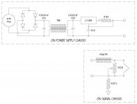
I am looking for a simple filament supply for the 26 that I can build with the parts I have on hand. I would appreciate any comments on this one. The diodes are high speed soft recovery types and the inductor has a ferrite rod core. I’m not really looking for ultimate performance just something quiet enough to get me started.
Thanks,
Marty
Thanks,
Marty
Attachments
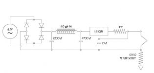
I am looking for a simple filament supply for the 26 that I can build with the parts I have on hand. I would appreciate any comments on this one. The diodes are high speed soft recovery types and the inductor has a ferrite rod core. I’m not really looking for ultimate performance just something quiet enough to get me started.
Thanks,
Marty
There'll be a little noise, I would expect, but there's no reason to hold you back on building. More L would help if the gyrator is out of reach. Increasing the C to at least 10000uF may also prove worthwhile.
Maybe look out for a logic level FET when you're next shopping, and work up a gyrator, if you want to go further.
I am looking for a simple filament supply for the 26 that I can build with the parts I have on hand. I would appreciate any comments on this one. The diodes are high speed soft recovery types and the inductor has a ferrite rod core. I’m not really looking for ultimate performance just something quiet enough to get me started.
Thanks,
Marty
I would up that inductor to a couple of mH as a minimum and increase the capacitance to 10,000uF or so, otherwise I think it would work ok. In this sort of application I usually use a voltage regulator ahead of the ccs to provide a little additional noise reduction.. Generally very quiet.
Small chokes (a couple of mH) between this supply and the filament will provide some isolation from high frequency line disturbances. (You can also use common mode choke and a single choke for both diff mode and common rejection improvements.)
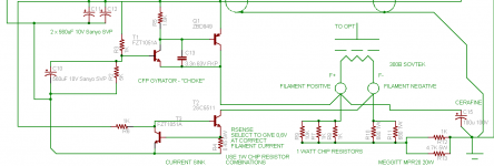
I also like to use a "pseudo" center tap across the filament using a pair of 22 ohm resistors connected to a 10 ohm resistor to gnd for measuring the cathode current. (Thevenin equivalent resistance seen by the cathode is about 21 ohms) Note that you do need to account for the filament current that flows through these resistors.
Thanks for the help guys. I went back to the junk drawers and I could do this with the parts I have. Unfortunately though it brings up a few more questions. Is there a problem with using the 100 Ohm 2W pot rather than a pair of 22 Ohm resistors?
Kevin, when you say that I need to “account for the filament current that flows through these resistors” Do mean that I need to adjust R set or that I need to account for the plate current flowing through the resistors that make the ct when I measure bias? Or….both? I have to admit that when there are multiple sources of current in a network I am totally lost.
Thanks Again,
Marty
Attachments
Is there a problem with using the 100 Ohm 2W pot rather than a pair of 22 Ohm resistors?
Kevin, when you say that I need to “account for the filament current that flows through these resistors” Do mean that I need to adjust R set or that I need to account for the plate current flowing through the resistors that make the ct when I measure bias? Or….both? I have to admit that when there are multiple sources of current in a network I am totally lost.
You have two current paths: Current that flows from the B+ supply, through the plate, through the filament and cathode resistor, then to the B+ return. In the filament supply path, current flows through the filament from the filament supply, and is returned to the supply.
I think that the 100R pot should be OK. As it concerns the plate current loop, the 100R pot is essentially two parallel 50R resistors, that are then in series with the 10R resistor (this assumes that the pot is near center). It will move your bias point a bit, as your cathode resistor will be in effect 25R+10R.
The 100R pot (doesn't matter where it's set) will be in parallel with the filament, in the heater supply current loop. Since the filament has a resistance of about 1.5R under operating conditions (1.5V at about 1A), you can probably assume that the parallel 100R will not be significant.
Sheldon
Going back to the question of using common mode chokes, when I was trying out different kinds of filament supply with an EE friend (from this site) we found that putting a common mode choke AFTER the LM1085 ccs degraded the sound, so we left it out - seemed that the ccs needs to be the last link in the chain. We didn't try out various points of putting the CMC before the ccs. On the other hand the CMC improved the sound when used as the last element after a voltage reg used in the usual way.
andy
andy
andy
andy
Apropos Pots and resistors across the filament. Heating with CCS can make DHTs sound much better than ac-heat - but (on the DHTs I've worked with) connecting a resistor across the filament can undo some of the advantage.
With 300Bs and CV1166s ( = Tungsram LP2) the resistor should be more than about 500 Ohms. I haven't experimented with the 26 (would like to now!) but would suggest using a higher value than 100Ohm, at least as an experiment. also, try just connecting the cathode resistor/cap to the negative side only, and compare the sound.
The macro difference between current source heating against dc (voltage) or ac is that the CCS presents a high dynamic impedance to the filament, over all audio frequencies. Perhaps there is a natural distribution of the cathode current across the cathode coating that is disrupted by low dynamic impedance schemes?
One thing I do know: if you convert a 300B amp to CCS heat, you can sit back and enjoy better sound. But if you then connect 1uF across the filament, the sound degrades all the way down to ac-heat level, and maybe even lower.
One thing I do know: if you convert a 300B amp to CCS heat, you can sit back and enjoy better sound. But if you then connect 1uF across the filament, the sound degrades all the way down to ac-heat level, and maybe even lower.
Very interesting. Could you provide a schematic of your circuit please? Do you mean 1uf to ground or to pins 1,4? With our without any resistors attached to the cathode? (fixed bias?)
Thank you, as I like to directly ground one pin of the filament while using CCS supply, and am curious of your findings.
Last edited:
Very interesting. Could you provide a schematic of your circuit please? Do you mean 1uf to ground or to pins 1,4? With our without any resistors attached to the cathode? (fixed bias?)
Thank you, as I like to directly ground one pin of the filament while using CCS supply, and am curious of your findings.
I use cathode bias, with resistors on both sides. They are different values, to let the cathode current make two voltage drops, 5V apart. The values are on the schematic.
Connecting the 1uF from F- to F+ wrecks the sound! I do have a cathode bias cap though - this old schematic shows it on the +ve side, but I think I found the -ve side sounds better.
Attachments
- Home
- Amplifiers
- Tubes / Valves
- #26 pre amp