Just finished purchasing Rod's regulator boards.
I believe I will use some regulator VR tubes for my HV B+. Looking at Coolzero's power supply diagram it shows he used a CCS before his regulator tubes.
Suggestions would be appreciated for the CCS as I have zero experience here.
I believe I will use some regulator VR tubes for my HV B+. Looking at Coolzero's power supply diagram it shows he used a CCS before his regulator tubes.
Suggestions would be appreciated for the CCS as I have zero experience here.
HV CCS is fairly easy to build using IXYS 10M45 and Supertex DN2540 in cascode.
Just using another DN2540 instead of the parallel 10M45 will be fine in case of the 6 to 10mA #26 circuit.
Example circuit:
http://www.diyaudio.com/forums/everything-else/196586-cascode-ccs-idea.html#post2709818
The unlabelled resistor network takes values according to the current you need, from the curves in the DN2540 datasheet, or from other's suggestions, eg:
http://www.diyaudio.com/forums/tubes-valves/106202-dn2540.html#post2766536
IXYS and Supertex parts are available at Mouser.
This simple gyrator performs beautifully. I tested it with 4P1L, 01a, 30, 46, 112a and 26. Better performance and sound if connected as mu follower
http://www.diyaudio.com/forums/tubes-valves/190857-4p1l-dht-line-stage-17.html#post2806222
Happy new year to all!
Cheers,
Ale
http://www.diyaudio.com/forums/tubes-valves/190857-4p1l-dht-line-stage-17.html#post2806222
Happy new year to all!
Cheers,
Ale
Rod,
Do you have a board available for this?
You could contact K & K Audio - Lundahl Transformers, audio DIY kits and more for kits
This simple gyrator performs beautifully. I tested it with 4P1L, 01a, 30, 46, 112a and 26. Better performance and sound if connected as mu follower
http://www.diyaudio.com/forums/tubes-valves/190857-4p1l-dht-line-stage-17.html#post2806222
Happy new year to all!
Cheers,
Ale
Better than using the choke or output/it transformer?
Happy new year chaps!

In my opinion I do prefer the OT (LL1660 and filament bias). However, the mu-follower gyrator is very close to it.
Haven't done yet a side by side comparison 26 OT against gyrator version which I will do in the near future.
Ps: I'm still trying to recover from last night!
Cheers,
Ale
Haven't done yet a side by side comparison 26 OT against gyrator version which I will do in the near future.
Ps: I'm still trying to recover from last night!
Cheers,
Ale
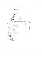
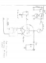
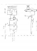
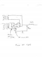
I'm going to post my power supply and my line stage chassis schematic in the hope that you guys in the know will look at it and tell me if I'm on the right track to start working on it.
The power supplies will be dual chassis dual supplies and the line stages will also be dual chassis. My reasoning is this... I would like to construct something without any cross talk and or noise.
The power transformers are an ebay purchase $20 Ea plus shipping. These will recitfy at 335VDC with #80 rectifier. They have no center tap so I added diodes also.
The filament transformers I purchased 30 yrs ago and I have about $12 in each of them. I have some mega 1500/450vdc 525vdc surge (Mallory)
I like the look of VR tubes so I incorporated (2) of them also.
The CCS plate supply is to be made up of two cascoded DN2540's. Schematic is on a prior post. Had sent an email to K&K Audio in the hope of purchasing two printed circuit boards with parts and heat sink. Received an email stating that they no longer use the DN2540 and the IXYS sounds better. See post 1488 for CCS plate supply. Added CCS to attached files.
Attachments

Last edited:
I like the multiple chassis plan.
Comments:
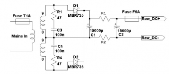
- where we have silicon rectifiers in a hybrid bridge, there may be some ringing in the transformer current during the turn-OFF of the rectifiers. The shape of the current pulse depends on the capacitance and inductance of the transformer, but it usually helps if you have 47nF (stacked MKT) and a series connected 47 to 100-ohm (carbon composition 0.5W) to snub out the pulses. If you can sense the dynamic current and view on a scope, you can optimise the values, but the ones given will work quite well in most cases. For the HV side a 1500V rated cap is required.
- If the Mallory caps are more than 5 years old, I would recommend avoiding them in audio circuits. Nothing sounds worse than stale Elkos. Mouser has Nichicon KX, and Panasonic TSHA/HB or TSUP and Farnell has the Panas, and these will be very hard to beat in the HV positions.
I think many folks like the IXYS FeTs in CCS circuit, so K & K's advice should be fine. I think that some IXYS types need a few more volts (gate-source) to regulate at 10mA. This is usually an advantage, since the lower cascode device then operates with higher Vds (means lower capacitance = better isolation).
Looks like you are ready to start building.... enjoy the work!
Comments:
- where we have silicon rectifiers in a hybrid bridge, there may be some ringing in the transformer current during the turn-OFF of the rectifiers. The shape of the current pulse depends on the capacitance and inductance of the transformer, but it usually helps if you have 47nF (stacked MKT) and a series connected 47 to 100-ohm (carbon composition 0.5W) to snub out the pulses. If you can sense the dynamic current and view on a scope, you can optimise the values, but the ones given will work quite well in most cases. For the HV side a 1500V rated cap is required.
- If the Mallory caps are more than 5 years old, I would recommend avoiding them in audio circuits. Nothing sounds worse than stale Elkos. Mouser has Nichicon KX, and Panasonic TSHA/HB or TSUP and Farnell has the Panas, and these will be very hard to beat in the HV positions.
I think many folks like the IXYS FeTs in CCS circuit, so K & K's advice should be fine. I think that some IXYS types need a few more volts (gate-source) to regulate at 10mA. This is usually an advantage, since the lower cascode device then operates with higher Vds (means lower capacitance = better isolation).
Looks like you are ready to start building.... enjoy the work!
Rod,
Thanks for the reply.
If I understand you correctly I need to build the filament supply to what you posted/schematic.
Don't know if I quite understand the change to the power HV supply. Is there another way for me to make it that would be better? Would like to stay with a tube rectifier but to be honest I haven't used a transformer without a CT before so this is all I could think of.
Yes, have a look at my 26 preamp HT supply here. I recommend adding a shunt regulator (e.g. Salas) for a quieter preamp ")
http://www.diyaudio.com/forums/showthread.php?p=2806229
Cheers, Ale
http://www.diyaudio.com/forums/showthread.php?p=2806229
Cheers, Ale
Is this what I need to do for the high voltage supply?
Yes, that looks good. The Fairchild UF4007 works well in this position.
With the RC-snubber, I believe that the hybrid bridge works just as well as the tube rectified full-wave circuit.
We are in good company, too:
Lundahl Transformers - Hybrid power supply
Ok, if I build the filament supply per your changes on the schematic you posted it will be good to go. Right?
Second, the changes to the HV supply the RC snubber and that will be good also.
Waiting to hear back on some CCS boards the IXYS fets you told me to go with.
Thinking along the lines of copper base plate with maybe Walnut base for the line stage chassis.
I appreciate the input and improvements that you told me about. I really feel like the humming #26 will finally get completed and I can complete a project that I started years ago.
One more thing.... should I be thinking about a AZ1 rectifier instead of the #80 I was going to use?
Ok, if I build the filament supply per your changes on the schematic you posted it will be good to go. Right?
Yes. Be sure to use the Hammond choke (28mH at 3A) to ensure that it bucks the voltage down to about 17V.
Second, the changes to the HV supply the RC snubber and that will be good also.
Waiting to hear back on some CCS boards the IXYS fets you told me to go with.
Thinking along the lines of copper base plate with maybe Walnut base for the line stage chassis.
Copper base will be useful as well as beautiful. May need varnish or some protection though!
I appreciate the input and improvements that you told me about. I really feel like the humming #26 will finally get completed and I can complete a project that I started years ago.
One more thing.... should I be thinking about a AZ1 rectifier instead of the #80 I was going to use?
We should not have to tolerate humming 26s any more! Many builders here have got this right now.
I haven't compared the AZ1, but I know that some contributors have tried them.
- Home
- Amplifiers
- Tubes / Valves
- #26 pre amp