Member
Joined 2006
Member
Joined 2006
My DHT preamp is now complete and thanks so much to Rod's regulators, no hum~! I'm loving it!!!! 
As a reference, the hum level of my old 26 RC-coupled preamp connected to my Linkwitz Pluto (gainclones at last stage after the active x-overs) was absolutely unbearable (though when hooked up to a tube amp with higher input impedance it was acceptable), but hey almost no hum with these regulators yeah!!
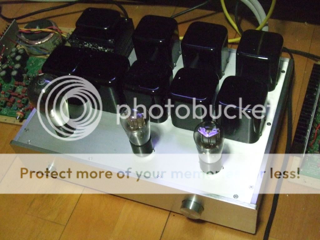
The current setting is: two 26 globes and a 381 half wave rectifier. It is a transformer in, transformer out, with a 200H choke loading to a parafeed output design....all these transformers were wounded by a friend with vintage German iron and English (Litz configured) wire...supposed be musical I was told..... So a total of 9 transformers, yike, so heavy...1 power, 2 filter chokes, 2 inputs, 2 ouputs and 2 loading chokes.... .
Oh, oh, I am already impressed after a couple hours of listening even though it was only born last week ---- very euphoric......despite no burn in of the cathode caps and transformers.....and do keep in mind there could be placebo effect on me as well, hehe....
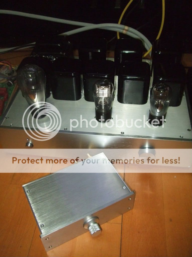
Photo - front: TVC volume control wounded by the same friend for mating with the preamp
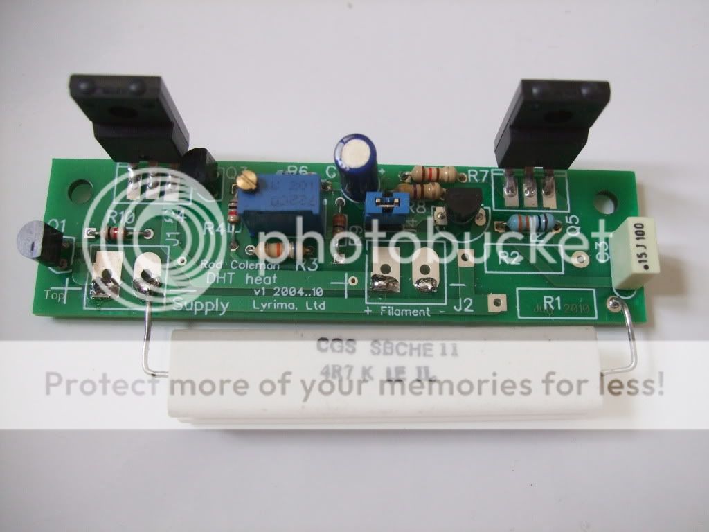
Photo - back: The DHT preamp - for 26/ 01A tube- switchable with the jumper in Rod Coleman's filament regulators inside
Will post the inner construction after opening it up
As a reference, the hum level of my old 26 RC-coupled preamp connected to my Linkwitz Pluto (gainclones at last stage after the active x-overs) was absolutely unbearable (though when hooked up to a tube amp with higher input impedance it was acceptable), but hey almost no hum with these regulators yeah!!
The current setting is: two 26 globes and a 381 half wave rectifier. It is a transformer in, transformer out, with a 200H choke loading to a parafeed output design....all these transformers were wounded by a friend with vintage German iron and English (Litz configured) wire...supposed be musical I was told..... So a total of 9 transformers, yike, so heavy...1 power, 2 filter chokes, 2 inputs, 2 ouputs and 2 loading chokes....
. Oh, oh, I am already impressed after a couple hours of listening even though it was only born last week ---- very euphoric......despite no burn in of the cathode caps and transformers.....and do keep in mind there could be placebo effect on me as well, hehe....
Photo - front: TVC volume control wounded by the same friend for mating with the preamp
Photo - back: The DHT preamp - for 26/ 01A tube- switchable with the jumper in Rod Coleman's filament regulators inside
Will post the inner construction after opening it up
Member
Joined 2006
My DHT preamp is now complete and thanks so much to Rod's regulators, no hum~! I'm loving it!!!!
As a reference, the hum level of my old 26 RC-coupled preamp connected to my Linkwitz Pluto (gainclones at last stage after the active x-overs) was absolutely unbearable (though when hooked up to a tube amp with higher input impedance it was acceptable), but hey almost no hum with these regulators yeah!!
The current setting is: two 26 globes and a 381 half wave rectifier. It is a transformer in, transformer out, with a 200H choke loading to a parafeed output design....all these transformers were wounded by a friend with vintage German iron and English (Litz configured) wire...supposed be musical I was told..... So a total of 9 transformers, yike, so heavy...1 power, 2 filter chokes, 2 inputs, 2 ouputs and 2 loading chokes....
Oh, oh, I am already impressed after a couple hours of listening even though it was only born last week ---- very euphoric......despite no burn in of the cathode caps and transformers.....and do keep in mind there could be placebo effect on me as well, hehe....
Photo - front: TVC volume control wounded by the same friend for mating with the preamp
Photo - back: The DHT preamp - for 26/ 01A tube- switchable with the jumper in Rod Coleman's filament regulators inside
Will post the inner construction after opening it up
Very nice! I would seriously recommend that you try battery bias of the grid instead of bypassed resistor in the cathode. If you don't like the idea of battery, LED could still be an option. I have found both battery and LED bias to be much much better than cathode bias in every way.
-MW
Very nice! I would seriously recommend that you try battery bias of the grid instead of bypassed resistor in the cathode. If you don't like the idea of battery, LED could still be an option. I have found both battery and LED bias to be much much better than cathode bias in every way.
-MW
I'll second that for most applications as one of the loudest and most vocal proponents here of fixed bias whether by battery or psu..
I'll second that for most applications as one of the loudest and most vocal proponents here of fixed bias whether by battery or psu..
I am at a bit of an advantage in that I use a transformer based volume control, and can float the grid without a coupling cap. Hard to beat! You could try the same by isolating the input with a transformer instead of a cap.
About temperature...
Hi Rod,
I've been watching for a while, about all the good words for your good works. Congratulations.
I'm not familiar with SS stuff, here's a very basic question for you.
Sorry for late to the party, the following quote is several pages back:
And I've also read in another post about a very high tolerable temperature of a transistor's case (not die), over 100'C IIRC...
A metal surface temperature higher than 65'C is very hot to touch already. 85 should be untouchable. SS parts which are too hot to touch always worry me very much. And, for almost all tube amplifiers, SS parts are mounted inside the chassis. So, components of such high temperature in the pot can not be a good thing - dried out electrolyte caps, crisp insulations... etc.
In your experiences, is it OK for such high temperature in long term stablity or safety? For the filament supply modules, and for the whole amps.
Thank you very much,
CLS
Hi Rod,
I've been watching for a while, about all the good words for your good works. Congratulations.
I'm not familiar with SS stuff, here's a very basic question for you.
Sorry for late to the party, the following quote is several pages back:
...
KM75 is in the picture, tested for 24 hours at 6V headroom in a 300B configuration, where the heatsink reached about 85 deg C in a 25 deg C environment.
And I've also read in another post about a very high tolerable temperature of a transistor's case (not die), over 100'C IIRC...
A metal surface temperature higher than 65'C is very hot to touch already. 85 should be untouchable. SS parts which are too hot to touch always worry me very much. And, for almost all tube amplifiers, SS parts are mounted inside the chassis. So, components of such high temperature in the pot can not be a good thing - dried out electrolyte caps, crisp insulations... etc.
In your experiences, is it OK for such high temperature in long term stablity or safety? For the filament supply modules, and for the whole amps.
Thank you very much,
CLS
High case temperatures are possible for power-transistors, but this must be part of an overall design. Especially, with the isolated TO-220 type, there is a larger difference between die temperature and case temp. So, depending on the power level the temperature may not exceed 100 deg C, or less.Hi Rod,
I've been watching for a while, about all the good words for your good works. Congratulations.
I'm not familiar with SS stuff, here's a very basic question for you.
Sorry for late to the party, the following quote is several pages back:
And I've also read in another post about a very high tolerable temperature of a transistor's case (not die), over 100'C IIRC...
A metal surface temperature higher than 65'C is very hot to touch already. 85 should be untouchable. SS parts which are too hot to touch always worry me very much.
For the regulators, the target heatsink should keep the temperature below 65 deg C. Of course, a lower temperature gives a wider safety margin, and this is to be welcomed in an amplifier design. Using 3mm or even 5mm aluminium for the amplifier chassis (backplate, or baseplate) will present an easy way to keep your semis below 50 deg C.
And, for almost all tube amplifiers, SS parts are mounted inside the chassis. So, components of such high temperature in the pot can not be a good thing - dried out electrolyte caps, crisp insulations... etc.
In your experiences, is it OK for such high temperature in long term stablity or safety? For the filament supply modules, and for the whole amps.
No, it is not OK for the internal temperature of an amplifier to reach, say 70 deg C. You must prevent this by using ventilation, and heatsinking.
If your amp is very crowded inside, the heatsink should be part of the rear panel, so that the heat escapes to the back.
In any case, a sealed amplifier chassis is asking for trouble - transformers and rectifiers will also get hot, and ventilation must be arranged for these.
Be careful with electrolytic capacitors. Please use parts that have a Ripple-Current rating that is higher than the rms ripple in your design. The PSUDii software will show the rms value of ripple current in all of your power supplies, including the raw dc supply for the DHT regulators. If you want a rule of thumb - the rms ripple current = DOUBLE the dc current.
Many electrolytics give a specification for the lifetime of the capacitor versus ripple current, versus temperature. If you choose (say) an 85 deg C rated capacitor, and operate it at (say) 50 deg C maximum, and (say) half the rated ripple current, you will find that the capacitor will last a reasonable time - probably 10000 hours for a reasonable quality part. You must calculate all these parameters (or measure them), and choose your capacitor carefully.
If you choose unbranded capacitors that give no specification for ripple current, you will find that short lifetime, and venting of corrosive vapour into your amp chassis, will be the outcome.
The same approach applies to power resistors: these are specified for a temperature rise for the amount of power burned in them. Forget about "5W" resistors, find out the temperature rise and see if you can tolerate it. Use a larger part if marginal.
If you take this approach for all the parts in your chassis, and include plenty of apertures for ventilation, and draw heat away with well-positioned heatsinks, you won't have reliability problems. When the amp is built and working, be sure to monitor the internal temperature for a while, if there is any doubt.
Last edited:
Member
Joined 2006
Thanks eboz and Kevin.
I would certainly like to try it out sometime later....!!
The fact is, this preamp was built by a friend, and he, and other master, are, oh well, perhaps a bit old fashioned, and when I mentioned - how about using grid bias....and both shook their head, and said cathode bias would sound better....both masters have over 20 years of tube amp building experience and so didn't feel like challenging them then, so perhaps will play around with it later on I told myself ...
So, I will use Kevin's circuit as a reference..... but how would you connect the other end of the input transformer, in my case? Thanks for the advice : )
Last edited:
A new poison for you Tsang !!
Hi CF..
Congratulations on yr new kid on the block !
Once yr on this baby , there wuld be no return back !! Other line-amps wuld sound terrible !!
1)
I fully agree with Kevin's suggestion , use the battery bias !
2)
This is another poison level for you :
If you are on the 381 halfwave rectifier , - (which is a solid plate anode?) , try get yourself on the german Telefunken/Valvo/Loewe/Tekade RGN354 half wave with "meshplates".
You need to reduce a bit the rectifier heater supply (from 5V ? ) to 4V ( yu need to use two serialled 0.33 Ohm at each leg) of the german tube.
The "german rectifier meshplates" are way superior to the 81 type tube. Yu wuld be amazed !
Enjoy yr music !
Paul
Thanks eboz and Kevin.
I would certainly like to try it out sometime later....!!
The fact is, this preamp was built by a friend, and he, and other master, are, oh well, perhaps a bit old fashioned, and when I mentioned - how about using grid bias....and both shook their head, and said cathode bias would sound better....both masters have over 20 years of tube amp building experience and so didn't feel like challenging them then, so perhaps will play around with it later on I told myself ...
So, I will use Kevin's circuit as a reference..... but how would you connect the other end of the input transformer, in my case? Thanks for the advice : )
CFT: I think that not many people use an input transformer for the sole purpose of blocking DC. Many use one to go from balanced input to unbalanced, but it could also simply be used as a 1:1 input. You would use the grid leak resistor to set the input impedance and connect the bottom leg of the resistor with the battery there. This could very well sound a lot better than using a cap for blocking DC.
BTW I thought you made a mistake by saying you are using a half wave rectifier. I guess that is in fact what you're using, but it's rare that I've seen it used for B+.
Last edited:
Hi CF....
If you then are on a fullwave rectifier, yu can try out the german/european ( Phillips, Valvo, Telefunken, Loewe, Tekade) AZ1 meshplates.
In the same genre family you will have the RGN 1054 or 1064 meshplates, the AZ11 meshplates.
I tried various rectifiers and settled on a AZ1 Valvo meshplate. You shuld at least try out the meshplate versions ! They mad4e a real difference
Chiao
Paul
Member
Joined 2006
Hi Paul, nice to hear from you here. Your DHT26 webpage is another inspiration
Yeah? definitely will check RGN354 out!!
Though I recall that the master said those German rectifiers might not be a best fit sonically with the American 26, 01A, etc..... for Ba (with a tip) that will be very nice he said.....and he has built quite a few of them...including a preamp with Ba driving a 45...... ( and hey, it might not be completely true....along with cathode bias... ) anyway will try that out if not too expensive.....
And hi eboz, the input transformer also provides some gain....thanks for the info here, definitely will look into grid battery bias
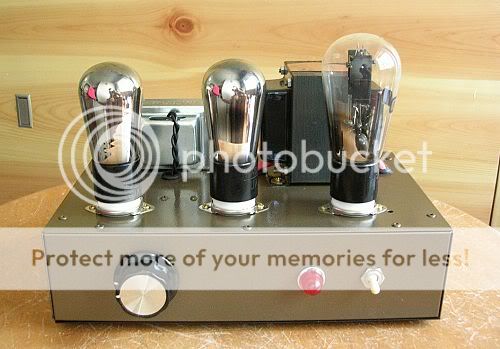
BTW, the 381 is indeed a half wave rectifier which I was told sounds better than using a full wave one, like the 380 employed in my older 26 preamp shown.
Yeah? definitely will check RGN354 out!!
Though I recall that the master said those German rectifiers might not be a best fit sonically with the American 26, 01A, etc..... for Ba (with a tip) that will be very nice he said.....and he has built quite a few of them...including a preamp with Ba driving a 45...... ( and hey, it might not be completely true....along with cathode bias...
) anyway will try that out if not too expensive..... And hi eboz, the input transformer also provides some gain....thanks for the info here, definitely will look into grid battery bias
BTW, the 381 is indeed a half wave rectifier which I was told sounds better than using a full wave one, like the 380 employed in my older 26 preamp shown.
Last edited:
Those mesh plate rectifiers are indeed nice - have a special softer feel that is quite intoxicating. Strangely I'm getting very good results with a 5Y3GT - I'm using that right now even though I also have AZ1 mesh. It REALLY helps to have bigger chokes (at least 2) and choke input and also only polypropylene caps in the PSU - I use motor runs. So LCLC. The difference is very audible.
andy
andy
Member
Joined 2006
I may be getting mixed up Andy but I seem to remember you trying a VR tube shunt power supply? I may well be wrong, but if so I'm interested in what you thought. I currently have a 26 as first pre stage with a voltage-dropping resistor and decoupling cap from the main 425V LCLC supply but was thinking I'd try an 0A2 or similar. Is this something you've tried?It REALLY helps to have bigger chokes (at least 2) and choke input and also only polypropylene caps in the PSU - I use motor runs. So LCLC. The difference is very audible.
Hi All,
Here's the results of my recent mods I have done for my pre.
1. Changed the 5Y3 rectifier tube in my HV supply to Type 80 - Considerable improvement over both the ends; top and bottom improved dramatically.
2. Replaced my filament supply with Rod's filament PSU -Thanks to Rod, this change made a huge difference. Overall sound became more natural and focused. I can say for sure, Rod's filament supply is without the doubt the best filament PSU I used so far with my 26 pre. Except for the fully choke loaded filament supply (which was mentioned in this thread before) I tried almost all the filament supplies available with my pre-amp prior to Rod's filament supply. Nothing came close. .
.
Big thanks to Rod for his kind assistance.
Here's the results of my recent mods I have done for my pre.
1. Changed the 5Y3 rectifier tube in my HV supply to Type 80 - Considerable improvement over both the ends; top and bottom improved dramatically.
2. Replaced my filament supply with Rod's filament PSU -Thanks to Rod, this change made a huge difference. Overall sound became more natural and focused. I can say for sure, Rod's filament supply is without the doubt the best filament PSU I used so far with my 26 pre. Except for the fully choke loaded filament supply (which was mentioned in this thread before) I tried almost all the filament supplies available with my pre-amp prior to Rod's filament supply. Nothing came close.
.Big thanks to Rod for his kind assistance.
Last edited:
- Home
- Amplifiers
- Tubes / Valves
- #26 pre amp