Hi Rod and Andy,
Thanks for answer.Yes I to have think about this problem and yeasterday I have puth than the diodes together without the testing board,so diode on diode with body like andy in the picture but without screws I have bolt diode on diode with fast glue and the problem is the same this 120hz hum.I even made the contact verry smal diode string to tube socket and diode string to ground conection is made direct with diode pins.I have now buy Miles wirewound resistor to make today the filament bias option,so lets se how this will turn out.But I will tray than the sic diode in filament bias also.Thanks guys for help.👍
Thanks for answer.Yes I to have think about this problem and yeasterday I have puth than the diodes together without the testing board,so diode on diode with body like andy in the picture but without screws I have bolt diode on diode with fast glue and the problem is the same this 120hz hum.I even made the contact verry smal diode string to tube socket and diode string to ground conection is made direct with diode pins.I have now buy Miles wirewound resistor to make today the filament bias option,so lets se how this will turn out.But I will tray than the sic diode in filament bias also.Thanks guys for help.👍
Hi Rod,
...some other question.When I use your regs for filament bias I use 3K3 resistor for R20 and for R1 I have 1,2 ohm wirewound 8watt.Resistor for filament bias will be 11ohm so I will go for starved filament 800mA.Plese tell me how I mist set the output regulator voltage.So must it be set to 10.3V this is 9V for bias and 1.3V for filament or must I just look when I medure the voltage around filament,that I become 1.3V when I set the reg.I will have about 16V out on raw supply.Plese for help.Thanks.
...some other question.When I use your regs for filament bias I use 3K3 resistor for R20 and for R1 I have 1,2 ohm wirewound 8watt.Resistor for filament bias will be 11ohm so I will go for starved filament 800mA.Plese tell me how I mist set the output regulator voltage.So must it be set to 10.3V this is 9V for bias and 1.3V for filament or must I just look when I medure the voltage around filament,that I become 1.3V when I set the reg.I will have about 16V out on raw supply.Plese for help.Thanks.
Hi euro21,
Thanks for answer.Tell me for what is the R105 there I dont see this resistor in Rods schematic using V7 reg for tube bias.There is only bias resistor from tube socket to ground.I dont see this resistor in Ale Moglias or Andy Evans design also.So when I see this right I must set the output voltage on the reg for about 10.3V ,so 9V for bias and 1.3V for filament.And the output voltage on raw supply must be 4-5V higher.Is this correct??
Thanks for answer.Tell me for what is the R105 there I dont see this resistor in Rods schematic using V7 reg for tube bias.There is only bias resistor from tube socket to ground.I dont see this resistor in Ale Moglias or Andy Evans design also.So when I see this right I must set the output voltage on the reg for about 10.3V ,so 9V for bias and 1.3V for filament.And the output voltage on raw supply must be 4-5V higher.Is this correct??
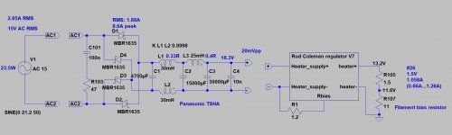
This is the #26 filament.what is the R105 there
Filament and filament bias resistor are serial, and R.C regulator current flow through both.
The voltage on the filament bias resistor (at 1.058A) 11.6V, and at the "output" of R.C. reg 13.2V. The difference is the filament voltage. If you decrease R.C. reg current (with trimpot), decreasing the bias and the filament voltage too.
In my practice the R.C. regulator "headroom" at least 5V.
I have V8 and also V7.I will use V8 in this 26 preamp.Are the settings diferent for V8 and V7??
V7 and V8 are the same for this calculation, so you can use the good example of euro21 for filament bias.
Hi Rod and euro21,
Thanks bout for answer.Yes I will go with 11ohm bias resistor becose I will go for first with starving filament 0.800A and for 11ohm this is caa.9V of bias.So I will set the output voltage on Rods reg for 10.3V like I say 9V for bias and 1.3 for filament.And if this will sound good,I will try than not starving the filament and will go for 1.05A for filament.I must listen to see if I can hear some diference.
Thanks bout for answer.Yes I will go with 11ohm bias resistor becose I will go for first with starving filament 0.800A and for 11ohm this is caa.9V of bias.So I will set the output voltage on Rods reg for 10.3V like I say 9V for bias and 1.3 for filament.And if this will sound good,I will try than not starving the filament and will go for 1.05A for filament.I must listen to see if I can hear some diference.
Hi Rod,
......oh yes,so I read this in Ale Moglias preamps design of starving filament.So If I will have no microphony I will go with normal 1.05 A filament.For now I will use 11 ohm bias resistor becouse I buy for each chanel 3 x 33 ohm Mils 12watt wirewound and I will put this in paralel.So for this bias resistor than I will set the reg out to 13.2V like euro21 sugested and raw supply to about 18V.Hope this works.I will now for first time using filament bias becose till today I only used normal battery grid bias with 26 tube,01a tube and other.Thanks guys for help.
......oh yes,so I read this in Ale Moglias preamps design of starving filament.So If I will have no microphony I will go with normal 1.05 A filament.For now I will use 11 ohm bias resistor becouse I buy for each chanel 3 x 33 ohm Mils 12watt wirewound and I will put this in paralel.So for this bias resistor than I will set the reg out to 13.2V like euro21 sugested and raw supply to about 18V.Hope this works.I will now for first time using filament bias becose till today I only used normal battery grid bias with 26 tube,01a tube and other.Thanks guys for help.
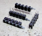
Here's one way to keep the SIC diodes close together...
That is quite clever!
Grid leak resistor
Hi Everyone,
Yesterday I moved my volume pot to the output of my 01a preamp. The input impedance of my amp is 1 meg, so having a 100k volume pot between the preamp and amp is fine. In fact it sounds quite fine this way!
In my set up this is certainly the right place for the potentiometer.
This morning I woke up and (for some reason) suddenly realized I forgot to add a grid leak resistor. It seamed to be completely well behaved all night, and sounded great. Why?
Is the preamp, in this configuration, now using the resistor-to-ground on the output of my phono pre as a grid-to-ground path? If that's the case, wouldn't this cause some ground loop issues?
Are there other explanations?
I am going to move the volume pot on my 26 preamp to the output, but this time I will install grid leak resistors.
Thanks in advance for your input!
Regards,
John
Starving the filament is usually tried to make a preamp a little less microphonic.
But the lifetime of the triode may be degraded.
Good to know, Rod, thanks to share the information.
I would like to post a tribute to Rod Coleman...
I am struck by Rod’s continued support and advice to many of us, with no sales and just pure audio-kindness.
Thank you Rod!
I would like to echo this. There are are quite a number of very knowledgeable and helpful people on this forum. Mr. Coleman is certainly exemplary of this tradition. Very generous. Thank you.
Regards,
John
Hello guys, Could you, please, suggest me which solution has better SQ: to use gyrator based on Ale Moglia or to use step down transformer 5.6:1. What is difference in SQ? I do understand these schematics have different gain. Need no gain actually, but i afraid there is bass roll off with transformer. I have both 26 and cx112a tubes.
- Home
- Amplifiers
- Tubes / Valves
- #26 pre amp